
Waveguide Switch or Coaxial Switch: Which One Should Route Your RF?
Waveguide switch vs coaxial switch: where each wins on power, loss, isolation and frequency, plus the crossover rule and a side-by-side comparison table for RF engineers.
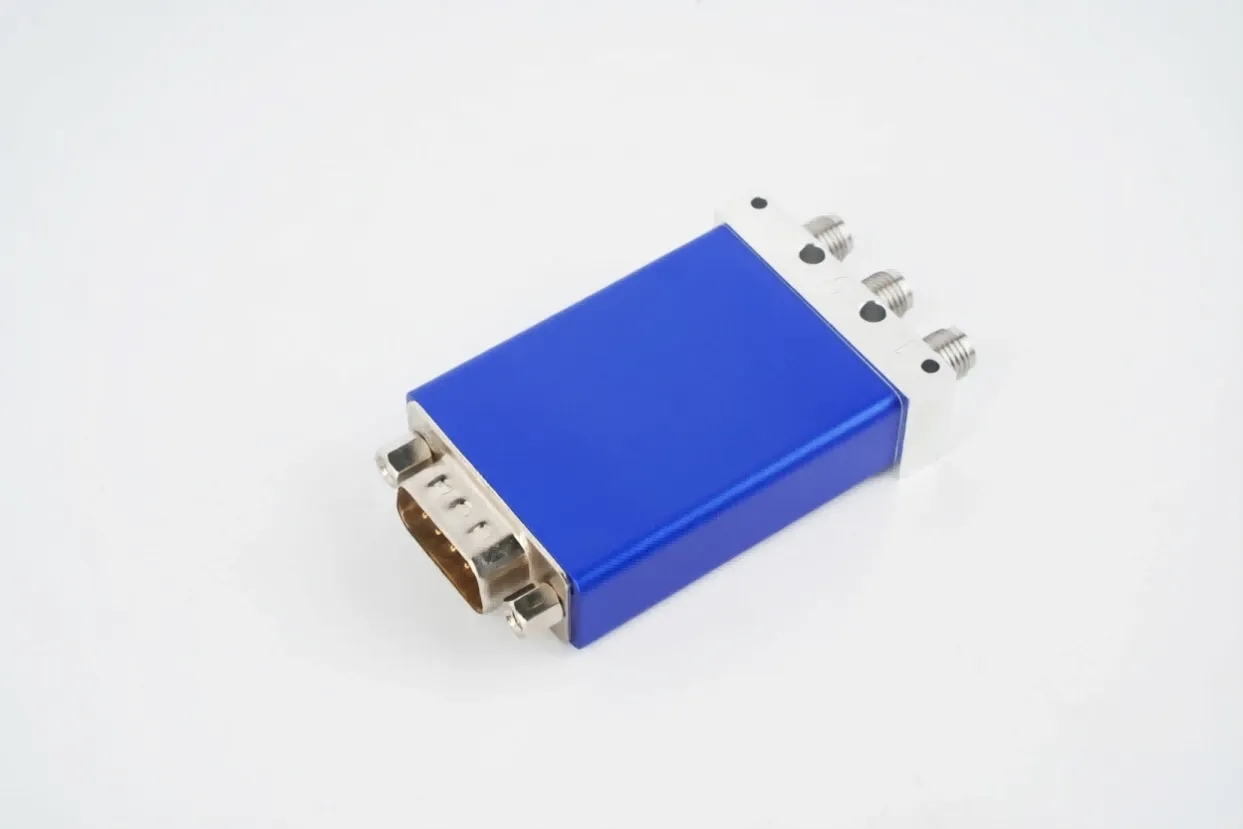
Waveguide Switch or Coaxial Switch: Which One Should Route Your RF?
Both devices move an RF signal from one port to another. The difference that matters is the transmission structure: a waveguide switch routes energy through a hollow metal guide, while a coaxial switch routes it along a center conductor inside a dielectric. That single difference decides where each one wins, and the right answer is almost never "always use the newer one."
What Each Structure Actually Does
A waveguide switch is an all-metal path with air inside. The signal travels through a hollow conductor, so the only loss comes from the resistance of the guide walls, and the power spreads across the whole inner surface. A coaxial switch carries the signal on a center conductor separated from the outer conductor by a dielectric. The center conductor is small, which makes the part flexible and compact, but it also concentrates the power on a thin surface.
Where a Waveguide Switch Wins
High power is the first win. In a coaxial switch the RF rides on the center conductor, so the power density is high and the failure mode at the top end is arcing and melting. In a waveguide the same power spreads over the inner walls, which pushes the breakdown threshold much higher. High-power coaxial switches typically handle hundreds of watts to a few kilowatts average, while waveguide switches in the same system class routinely handle several kilowatts average and far higher peaks.
Low loss at millimeter-wave frequencies is the second win. A coaxial dielectric has a loss tangent, so its loss climbs as frequency rises. A waveguide's loss stays flat, which is why the part that held 0.1 dB at 10 GHz is still near 0.1 dB at 40 GHz. Above roughly 20 to 40 GHz the coaxial path starts losing the race, and at 110 GHz on WR-10 it is simply waveguide territory.
Isolation is the third win. The open port of a waveguide switch is blocked by a physical slab of metal, which is why figures of 60 to 100 dB are normal. A coaxial switch relies on small contact points and typically lands in the 60 to 80 dB range. When the isolated port sits next to a sensitive receiver, that margin is the difference between a clean path and a damaged front end.
Where a Coaxial Switch Wins
Flexibility is the coaxial strength. A coaxial run snakes through tight spaces and needs no rigid flange alignment, which is why benches and mobile kits favor it. Bandwidth is the second strength: a coaxial connector family covers from DC to 40 GHz and beyond in one interface, while each waveguide size covers only its own band. Size, weight, and cost at low frequency are the third, and for an automated test bench the off-the-shelf coaxial ecosystem is hard to beat.
The Crossover Rule
Use waveguide above roughly 20 to 40 GHz or above a few kilowatts average, where coaxial dielectric loss and connector power handling turn against you. Use coaxial below that, where flexibility and cost win. Real systems are usually hybrid: waveguide on the high-power transmit path, coaxial on the auxiliary calibration and monitoring lines. The structure should follow the frequency and the power, not the catalog the buyer opened first.
Switching Speed and the Outdoor Question
Speed favors coaxial, especially solid-state versions that flip in nanoseconds to tens of milliseconds with no moving parts, but they pay for it in insertion loss and heat. Electromechanical waveguide switches move in tens of milliseconds, which is slow next to a PIN diode yet fast enough for any redundancy or test-routing job that is not pulse by pulse. Environment is the other divider: a waveguide switch can be weatherized and pressurized for an outdoor satcom earth station, while coaxial connectors have firmer ingress limits that push the sealed job back toward waveguide.
Waveguide Switch vs Coaxial Switch at a Glance
| Parameter | Waveguide switch | Coaxial switch |
|---|---|---|
| Transmission | Hollow metal guide, air | Center conductor plus dielectric |
| Frequency | Band-limited per WR size | DC to 40+ GHz in one family |
| Power handling | Several kW average, very high peak | Hundreds of W to a few kW average |
| Insertion loss trend | Flat into millimeter wave | Rises with frequency |
| Isolation | 60 to 100 dB | 60 to 80 dB |
| Form factor | Rigid, flanged | Compact, flexible |
| Best use | High power, mmW, radar, satcom | Low freq, test, flexible routing |
What AO Microwave Ships in Each World
We are a waveguide house, so the waveguide switch family is where the depth is, from WR-137 to WR-10 with latching or failsafe actuators. For the coaxial side of a hybrid build, the coaxial load and coaxial fixed attenuator lines cover termination and padding in the same rack, and the waveguide load closes the high-power end. The point is not to pick a brand, it is to pick the structure that matches the frequency and the power before you order either one, and our WR-22 DPDT switch shows what that looks like at Q band.
Frequently Asked Questions
Q: Can a coaxial switch replace a waveguide switch directly?
A: Only when the frequency and power sit inside the coaxial envelope, which means below roughly 20 to 40 GHz and below a few kilowatts average. Above that the dielectric loss and the connector power limit turn against the coaxial part, and the flange interface is different anyway, so it is rarely a drop-in swap.
Q: Why does coaxial loss get worse at high frequency?
A: The dielectric between the center and outer conductors has a loss tangent that absorbs RF energy and converts it to heat. That absorption grows with frequency, so a coaxial path that was fine at 6 GHz can lose a decibel or more per meter by the time it reaches millimeter-wave bands, while a waveguide stays nearly flat.
Q: Which switch handles more power?
A: The waveguide switch, almost always. The signal spreads across the inner walls instead of sitting on a thin center conductor, which lowers the power density and raises the arcing threshold. Coaxial switches are excellent at low power and high frequency, but they hit a hard ceiling on average and peak power.
Q: Is waveguide always better for radar?
A: For the high-power transmit and receive paths, yes, because radar needs low loss, high isolation, and kilowatt-class handling. The auxiliary lines, calibration paths, and monitoring taps are often coaxial, so a radar front end is usually a mix of both rather than one technology everywhere.
Q: Do I need both types in one system?
A: Many systems do. A common layout runs waveguide on the main high-power chain and coaxial on the test, calibration, and monitoring branches, because each structure is used where it is strongest. The crossover is set by frequency and power, not by preference.
Q: What frequency is the crossover between coaxial and waveguide?
A: A practical line sits around 20 to 40 GHz and a few kilowatts average. Below it, coaxial wins on flexibility and cost. Above it, waveguide wins on loss and power handling. The exact point depends on your loss budget and the peak power the path must survive.
Not Sure Which Structure Fits Your Path?
Tell us the frequency, the power, and the layout. We will point to the right transmission structure and return a datasheet within 24 hours.
Contact Our Engineering Team