
How Much Amplifier Power Does Your IEC 61000-4-3 Immunity Test Really Need?
How much amplifier power does an IEC 61000-4-3 immunity test need? Work the free-space formula, add AM envelope, loss and mismatch, and size the amp for 10 V/m at 3 m.
How Much Amplifier Power Does Your IEC 61000-4-3 Immunity Test Really Need?
The free-space formula says a 10 V/m field at 3 m from a 10 dBi horn takes roughly 3 W of radiated power. No compliance lab runs a 3 W amplifier. The 80% AM envelope, feed line loss, mismatch and band-edge gain sag sit between that number and the amplifier you actually buy, and together they turn 3 W into tens of watts. Push the level to 30 V/m and you are into the hundreds; push to the 200 V/m that MIL-STD-461 RS103 demands on some platforms and you are shopping for a kilowatt. Here is the arithmetic chain, so you size the amplifier once instead of twice.
Start With the One Formula
In free space, the field strength at distance d from a radiator delivering power P through an antenna of gain G follows E = sqrt(30 · P · G) / d, with E in V/m, P in watts, G as a linear ratio and d in meters. Rearranged for the power you need at the aperture: P = E² · d² / (30 · G). Run it for the common targets at 3 m, which is the standard test distance for IEC 61000-4-3:
| Field target | Distance | Radiated power at 8 dBi | Radiated power at 10 dBi |
|---|---|---|---|
| 3 V/m | 3 m | 0.4 W | 0.3 W |
| 10 V/m | 3 m | 4.8 W | 3.0 W |
| 30 V/m | 3 m | 43 W | 27 W |
| 200 V/m (RS103 class) | 1 m | 212 W | 133 W |
Those are radiated powers at the aperture, the power actually leaving the horn. Everything that follows is the distance between that number and the amplifier's output connector.
The Four Multipliers Between Formula and Amplifier
1. The 80% AM envelope. IEC 61000-4-3 modulates the carrier at 1 kHz with 80% depth, so the field the probe reads is the RMS of a signal swinging through a 1.8:1 envelope. The carrier has to carry that swing, and labs budget roughly two to three times the free-space number in headroom for it. The modulation is not a footnote; it is the difference between a 5 W estimate and a 15 W one.
2. Cable and tuner loss. Every decibel between the amplifier and the aperture is a decibel of field you buy back with power. A 2 dB feed line costs a factor of 1.6; a careless 3 dB run costs 2. High-frequency runs at 18-40 GHz lose more per meter than the same cable at 1 GHz, and the loss climbs again when the cable is coiled for the chamber door.
3. Mismatch at the antenna. A double-ridged horn antenna specified at 2.5:1 maximum reflects about 18% of the forward power back at the worst frequency, because the reflection coefficient grows to 0.43 and power follows its square. A 2.0:1 model reflects about 11%. That power never radiates, so the amplifier has to supply it anyway. The VSWR and return loss table converts any figure on a datasheet into reflected power.
4. Band-edge gain sag. A 1-18 GHz horn averages about 10 dBi, but it delivers roughly 6 dBi at 1 GHz where the aperture is electrically small. Your test plan does not care about the average; it cares about 1.4 GHz, where the standard asks you to prove immunity. Sizing on mid-band gain is the single most common way to undersize an amplifier. The climb is not a manufacturing defect; it is the direct consequence of the ridge loading that buys the bandwidth, and it is plotted model by model in what a double-ridged horn antenna is and how it covers 0.1 to 40 GHz.
Chain them for a real bench: 10 V/m at 3 m needs 4.8 W radiated at 8 dBi. Use the worst-case 6 dBi at the low edge instead and the radiated power doubles to about 9.5 W. Add the AM headroom and a 2 dB feed run and you are near 30 W. Add the mismatch margin and you are at 35 to 40 W. That is why a sensible quotation for a 10 V/m bench is a 40 to 50 W amplifier, not a 5 W one.
The Levels You Are Designing Against
| Standard | Field levels | Frequency span | Typical distance |
|---|---|---|---|
| IEC 61000-4-3 | 1, 3, 10, 30 V/m, plus an open level | 80 MHz-6 GHz legacy, extended upward in the 2020 edition | 3 m |
| MIL-STD-461 RS103 | 5 to 200 V/m, platform dependent | 30 MHz-18 GHz required, 18-40 GHz tailored | 1 m |
The 80% AM at 1 kHz applies to the IEC method throughout. RS103 is a CW requirement at the stated level, which is why its 200 V/m at 1 m is a kilowatt-class problem rather than a hundred-watt one.
Picking the Horn for the Field You Need
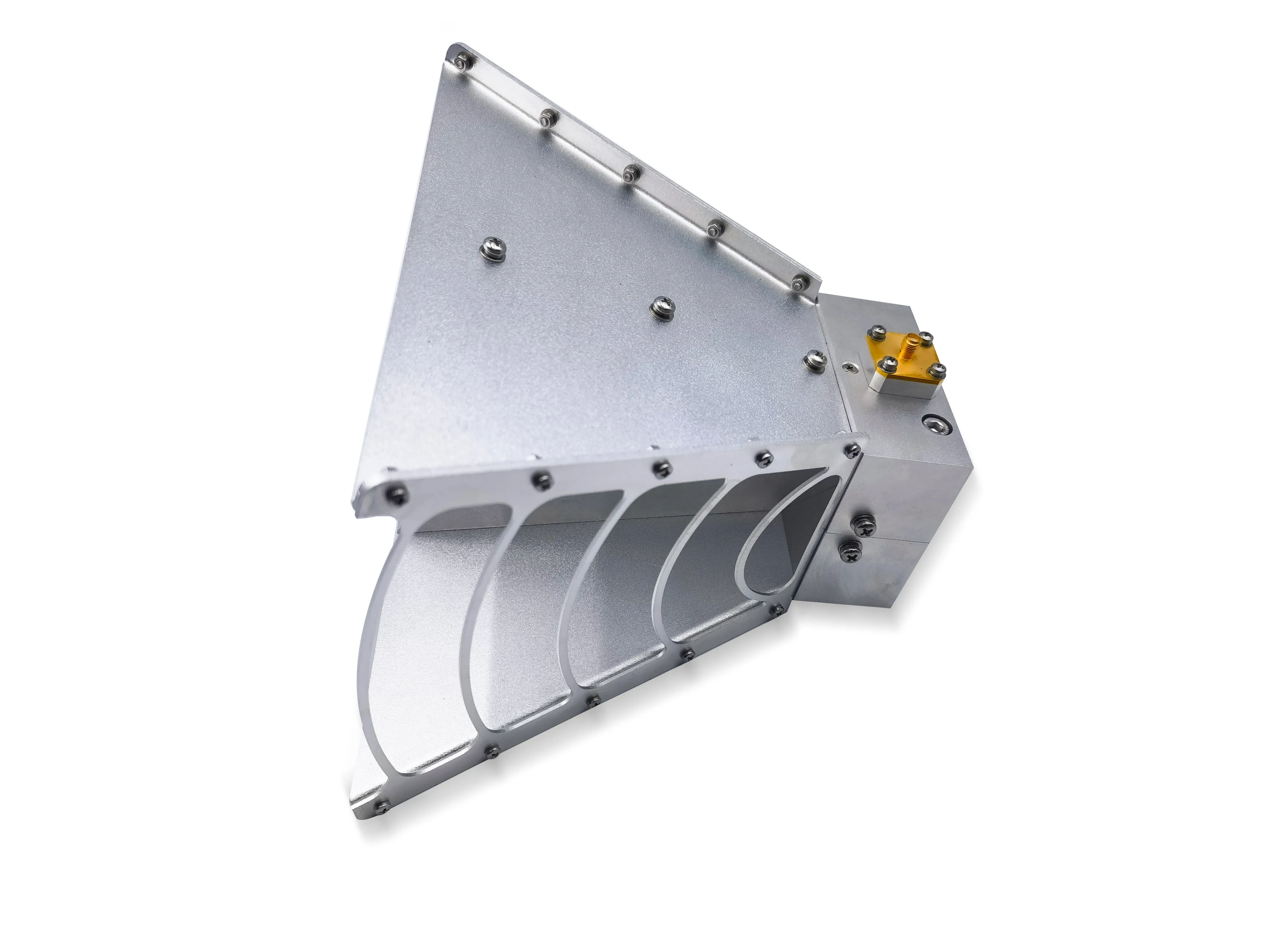
Three constraints pick the horn before the amplifier does. First, the lowest frequency in the test plan: for the legacy IEC range, the AO Microwave 0.6-6 GHz double-ridged horn antenna covers 80 MHz to 6 GHz from one aperture, and broader plans move to the 1-18 GHz models with their 10 dBi average gain. Second, the beamwidth: a 15 or 16 dBi horn at 18-40 GHz throws a 10 to 20 degree beam, which will not uniformly fill a test volume at 3 m, so chamber geometry can force the lower-gain, wider-beam choice. Third, power handling: peak power in these antennas is limited by the coaxial connector and its internal transition probe rather than by the horn itself, so a 200 V/m RS103 setup needs a conversation about the interface, not just the aperture. The double-ridged horn antenna selection guide matches bands to models, the double-ridged vs standard gain horn antenna comparison settles which family the bench needs in the first place, and the RF frequency bands table keeps the letter bands straight while you do.
A Worked Bench, Start to Finish
1. Fix the requirement: 10 V/m at 3 m, 80 MHz to 6 GHz, per IEC 61000-4-3.
2. Pick the horn: 0.6-6 GHz model, 10 dBi average, N female connector, with a calibrated gain curve for the serial number.
3. Compute radiated power at the worst frequency, not the average, and take the VSWR maximum from the datasheet as the mismatch case.
4. Add the multipliers: AM envelope headroom, measured feed line loss at the top of the band, and mismatch margin.
5. Size the amplifier one step above the result. A 35 W chain buys a 50 W amplifier, because a amplifier run at its limit drifts and fails at the worst time.
6. Verify with a field probe at the test volume, at the frequencies the formula was least confident about. The formula sizes the purchase; the probe proves the setup.
7. Between sweeps, park the transmitter on a matched coaxial load rather than an open port or a bare directional coupler output. An idle transmitter firing into a mismatched port is how amplifiers die between test runs.
Five Mistakes That Undersize the Amplifier
Sizing on mid-band gain. The average is a marketing number; the low edge is a physics number. Use the gain curve.
Forgetting the AM envelope. The 80% modulation is a power multiplier hiding in plain sight in the standard.
Ignoring mismatch at band edges. VSWR is worst where the horn is hardest to match, which is also where the standard sends you.
Mating N or SMA above their limits. Type N is commonly used to around 11 to 18 GHz and SMA to 18 GHz. Above that, 2.92 mm is not an upgrade, it is the only honest interface.
Hot-switching the signal path. Moving any electromechanical switch or rotor with RF live arcs the cavity. Silence the source, move, restore. That rule applies to the whole chain, not just the antenna.
Frequently Asked Questions
Q: How much power do I need for 10 V/m at 3 meters?
A: The free-space answer is about 3 to 5 W radiated with a 10 dBi horn. The bench answer is 40 to 50 W at the amplifier, once the 80% AM envelope, feed line loss, mismatch and band-edge gain sag are accounted for. Budget the second number.
Q: What is the 80% AM in IEC 61000-4-3?
A: The carrier is amplitude modulated at 1 kHz to 80% depth, so the field envelope swings through a 1.8:1 range while the probe reads an RMS level. The carrier must support the envelope, which is why the modulation translates directly into amplifier headroom.
Q: How much power does MIL-STD-461 RS103 need at 200 V/m?
A: At 1 m with an 8 dBi horn the formula wants about 212 W radiated, and a real chain with losses and margin lands in the 300 to 500 W class before you consider the connector and transition limits. RS103 levels are platform dependent, so confirm the level before sizing the amplifier.
Q: Does antenna VSWR affect the power I need?
A: Yes, directly. A 2.5:1 maximum reflects about 18% of forward power at the worst frequency, and the amplifier supplies that power without seeing any field from it. A 2.0:1 model reflects about 11%. Neither is a defect; both are the price of wideband coverage, and both belong in the power budget.
Q: Which horn covers the whole 80 MHz to 6 GHz IEC range?
A: The 0.6-6 GHz double-ridged model covers the legacy IEC 61000-4-3 span from a single aperture with 10 dBi average gain and an N female connector. Plans that extend above 6 GHz under the 2020 edition of the standard move to the 1-18 GHz models.
Q: Can I verify field strength without a field probe?
A: Not defensibly. The substitution method with a calibrated reference antenna gets you close, and the formula gets you a purchase order, but a report that claims 10 V/m needs probe data at the test volume. Budget the probe alongside the amplifier.
Sizing an Immunity Bench?
Tell us the standard, the field level, the test distance and your lowest frequency. We will confirm the horn, the connector and the power handling, and return the calculation with a datasheet within 24 hours.
Contact Our Engineering Team