
Flexible Twistable vs Seamless Waveguide: Which One Should You Choose?
Twistable vs seamless waveguide compared: power, pressurization, twisting, VSWR & price. Two-step selection guide with diagrams. Choose the right flexible waveguide.
Flexible Twistable vs Seamless Waveguide: Which One Should You Choose?
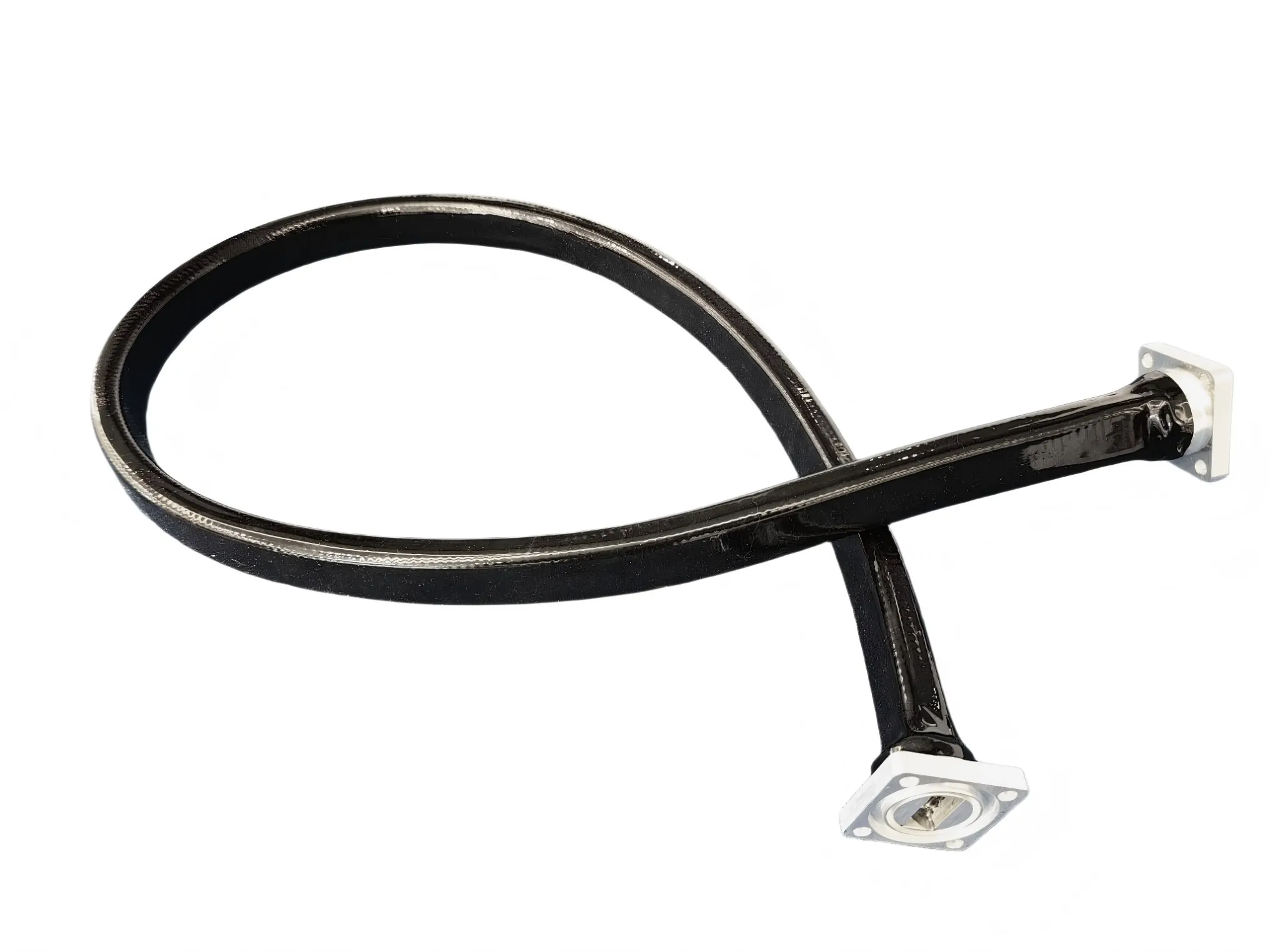
You've laid out the waveguide run, measured the flange-to-flange distance, and the rigid path simply will not conform. It kinks around a structural beam, the antenna vibrates on azimuth rotation, and two flanges sit a few millimeters off. The reflex is to reach for a flexible waveguide. But the moment you do, a second, less-obvious decision appears: which flexible construction? The twistable vs seamless waveguide split is what actually determines whether your run will hold pressure, survive high power, or align those misaligned flanges. The difference between a twistable and a seamless flexible waveguide is construction: a twistable waveguide is helically wound with interlocking bands that allow limited rotation, while a seamless waveguide is extruded from a single tube that holds pressure and handles high power but cannot be twisted at all.
Step 1: Why You Need a Flexible Waveguide
A rigid waveguide gives you the lowest insertion loss per meter. That's why transmitter feeds, antenna runs, and test benches default to it. But lowest loss buys mechanical unforgiveness. A straight waveguide, or a fixed waveguide E-bend and waveguide H-bend (or a custom waveguide E-bend and H-bend for non-standard angles), assumes the path is geometrically perfect: straight where it should be straight, bent at the exact angle the bend was brazed for, with flanges that mate flush. Real installations rarely cooperate.
The run has to clear a structural beam, dodge a coax feed, or accommodate a vibration-isolated pedestal that shifts a few millimeters under load. Thermal expansion moves flange positions between morning and midday. The antenna rotates, and the feed point shifts relative to the fixed transmitter.
That's the moment rigid routing runs out of road. On a shipboard X-band radar refit the author is familiar with, a 2-meter rigid WR90 run cracked at the E-bend brazed joint within three months because the pedestal shifted 3 mm under azimuth motor torque. The common waveguide routing problems (misalignment stress, flange arcing from uneven contact, hairline cracks at brazed joints) all trace back to forcing a rigid tube to follow a path it was never shaped for. Reaching for a flexible waveguide is the engineering reflex: trade a few tenths of a dB per meter for the freedom to bend in both E- and H-planes and absorb the misalignment the structure hands you.
Once that decision is made, the construction choice becomes the real one. It's binary: a twistable waveguide or a seamless waveguide. The two are not interchangeable, and picking the wrong one turns a small mechanical convenience into a power-handling or pressurization failure.
Step 2: Twistable vs Seamless Waveguide
Within flexible waveguides, the twistable vs seamless waveguide split comes down to how the tube is built. According to Microwaves101's flexible waveguide reference, three constructions exist (twistable, non-twistable, and seamless), but the practical decision narrows to two. Both constructions are defined under MIL-DTL-287, the U.S. military general specification for flexible, twistable and non-twistable waveguide assemblies, which formalizes the mechanical and electrical requirements each type must meet.
A flexible twistable waveguide is wound from a single silver-plated copper strip, pre-formed into a crimped seven-edge profile, then helically wound around an approximately rectangular mandrel. Adjacent windings interlock. That interlock is what lets the tube bend and also accept a limited twist, because torque lets the windings shift slightly relative to each other without opening an RF leak path. A flexible seamless waveguide is extruded from a single copper tube with no seam at all. The wall is formed into a continuous seamless corrugation that gives bending flexibility. But because there is no interlocking structure to absorb rotation, twisting it kinks and permanently deforms the tube.
Before studying the diagrams, narrow the decision with four questions:
- Do you need to twist? A few degrees to align misaligned flanges, or none at all?
- Do you need to pressurize? Dry-air or nitrogen purge for environmental protection?
- How much power? Low-power lab or inter-rack, or high-power transmitter feed?
- What's the budget? Helical winding is cheaper; extrusion plus brazed flanges is not.
Those four answers collapse the twistable vs seamless choice almost entirely. If you need pressurization or high power, the seam on a twistable section disqualifies it. If you only need to absorb a few millimeters of misalignment in a low-power run, paying for a seamless section is wasted budget.
Flexible Twistable Waveguide: Interlocking Helical Structure

Flexible Seamless Waveguide: Seamless Corrugated Tube

Twistable vs Seamless Waveguide: Side-by-Side Comparison
The flexible twistable vs seamless waveguide comparison comes down to seven criteria that map directly to the four decision drivers above. The table isolates each criterion for quick matching.
| Criterion | Flexible Twistable Waveguide | Flexible Seamless Waveguide |
|---|---|---|
| Bending | Yes: both E- and H-plane | Yes: both E- and H-plane |
| Twisting | Yes: limited, a few turns/m (interlock shifts) | No: torsion kinks / deforms the corrugation |
| Power Handling | Lower (helical seam concentrates current; can leak) | Higher (smooth inner wall, no seam) |
| Pressurization | No: seam not hermetic | Yes: hermetic jacket; dry-air / N2 purge (typical pressure rating to 30 PSIG, manufacturer-dependent) |
| Typical Insertion Loss | Higher (sliding contact points add loss) | Lower |
| Typical VSWR | 1.10 to 1.25:1 (catalog range; varies by WR size) | 1.05:1 or better |
| Price | Lower | Higher (extrusion + brazed flanges) |
| Typical Applications | Lab test, inter-rack, low-power radar modules | High-power radar feeds, SATCOM ground, mmWave test, pressurized runs |
As a reference, AO Microwave supplies both constructions across standard WR sizes. See their flexible twistable waveguide and flexible seamless waveguide pages for current specs (typical catalog values; verify against your WR size and frequency band before specifying).
Three conditional rules resolve most selections:
- Pressurized run? Choose seamless. The interlocking seam on a twistable section is not hermetic and will not hold a dry-air or nitrogen purge.
- Need a few degrees of twist to align misaligned flanges? A twistable flexible waveguide is your only option. A seamless section will kink and permanently deform before it gives you any rotational play.
- Above ~1 kW CW, seamless is the safe call. The helical seam on a twistable section concentrates current at the edges and can leak under fault conditions.
How to Choose: Matching the Type to Your Requirements
Walk the requirements in order of severity: power and pressurization disqualify options before misalignment and budget do.
Pressurized run → seamless. Any system that purges the waveguide with dry air or nitrogen must use a seamless flexible waveguide. That includes high-power radar feeds, SATCOM ground stations, and mmWave test stands in humid environments. The helical seam on a twistable section is not hermetic; it relies on an external jacket that is a wear item, not a pressure boundary. Typical seamless flexible waveguide pressure ratings reach 30 PSIG (manufacturer-dependent). Twistable sections cannot sustain pressure without an external jacket. (For more on jackets and pressurization, see the RF Essentials flexible waveguide glossary.)
High-power transmitter runs follow the same logic. Above roughly 1 kW CW (typical catalog threshold; varies by WR size and frequency), the sliding contact points on a twistable section's interlock concentrate current, raise insertion loss, and become a leak path under fault conditions. A seamless section's smooth inner wall keeps current distribution uniform. A SATCOM ground station that specified twistable for a pressurized L-band feed learned this the hard way: the seam weeped moisture within six months, and the section was replaced with seamless at the next maintenance window.
Continuous rotation is a different problem entirely. Both flexible constructions handle static misalignment, not spinning antennas. A twistable waveguide accepts a few turns per meter of limited twist; if the antenna rotates continuously, step up to a waveguide rotary joint designed for that duty cycle.
At the other end of the spectrum, lab and inter-rack runs with minor misalignment are where twistable shines. Test setups, equipment-cabinet jumpers, and low-power radar modules where a flange sits a few millimeters off are the natural home for a twistable flexible waveguide. The twist absorbs the misalignment, the lower cost is welcome, and the higher insertion loss is acceptable because the run is short and the power is low.
If you try to twist a seamless waveguide anyway, the corrugation kinks almost immediately. The deformation is permanent, the VSWR degrades, and the section is scrap. The same hidden routing errors that forced you off rigid in Step 1 are the ones you're now absorbing, so get the construction right the first time.
Frequently Asked Questions
Q: Can you twist a seamless flexible waveguide?
A: No. A seamless flexible waveguide cannot be twisted, because the continuous corrugated wall has no interlocking structure to absorb rotation, so torsional load transfers directly into the corrugation and permanently kinks the tube. Bending is fine; rotation about its axis is not.
Q: Which flexible waveguide is best for pressurized runs?
A: A flexible seamless waveguide is the correct choice for any pressurized waveguide run. Its single-tube construction forms a hermetic jacket that holds dry-air or nitrogen purge, with typical pressure ratings reaching 30 PSIG (manufacturer-dependent). The helical seam on a twistable section is not hermetic and cannot sustain the pressure differential a pressurized run requires.
Q: Why does a twistable waveguide have higher insertion loss than a seamless one?
A: A twistable waveguide has higher insertion loss because its interlocking helical windings create sliding contact points that add resistive loss, whereas a seamless waveguide's smooth inner wall keeps current distribution uniform. The gap widens at Ka-band and above, where every contact point becomes a measurable loss contributor. Typical twistable waveguide VSWR runs 1.10 to 1.25:1 (catalog range); seamless achieves 1.05:1 or better.
Q: Is twistable or seamless flexible waveguide better for radar and SATCOM?
A: For radar and SATCOM, seamless is almost always the right call. Those systems typically run high power, require pressurization for environmental protection, and cannot tolerate the leak paths a twistable seam introduces. (For the broader TX/RX separation architecture these feeds plug into, see circulators in radar and satellite systems.) A twistable flexible waveguide is acceptable only in low-power radar modules or test and lab positions where those constraints do not apply.
Q: How much more expensive is a seamless flexible waveguide?
A: Extrusion from a single copper billet plus brazed flanges costs more than helical winding from a strip. That is why a seamless flexible waveguide carries a higher price tag than a twistable section of the same WR size. Exact pricing is manufacturer- and WR-size-dependent; confirm at quote.
Conclusion
The decision is genuinely two steps, not one. First, confirm the rigid run won't follow the actual installation path and reach for a flexible waveguide. Second, within flexible constructions, let power and pressurization do the disqualifying for you. Pressurized or high-power runs force seamless; lab, inter-rack, or low-power runs with flange misalignment are the natural home of twistable. Continuous rotation belongs to a rotary joint.
Not Sure Whether to Spec Twistable or Seamless?
AO Microwave ships both flexible twistable and flexible seamless waveguide across standard WR sizes. Tell us your frequency band, average/peak power, pressurization target, and the routing geometry. Engineering typically responds within one business day.
Contact AO Microwave