Professional Manufacturer and Supplier of RF & Microwave Solutions
We provide high-performance Waveguide, RF Coaxial, Antenna and Cable solutions with fast delivery, strict quality control and flexible customization for global customers.


We provide high-performance Waveguide, RF Coaxial, Antenna and Cable solutions with fast delivery, strict quality control and flexible customization for global customers.

Our product range includes Waveguide components, Coaxial components, RF cables, Antennas and customized microwave assemblies.

With experienced engineering teams, strict quality inspection and efficient production processes, we help customers shorten lead time and reduce project risk.
Why Choose Us
Professional and Reliable RF & Microwave Solutions
Professional technical solutions from design to final production.
Strict inspection processes ensure consistent performance.
Efficient scheduling enables short lead time and on-time shipment.
Standard and custom solutions to meet diverse requirements.
By the numbers
We measure the business by useful products, dependable partners, and customers who come back when they need the next everyday piece.

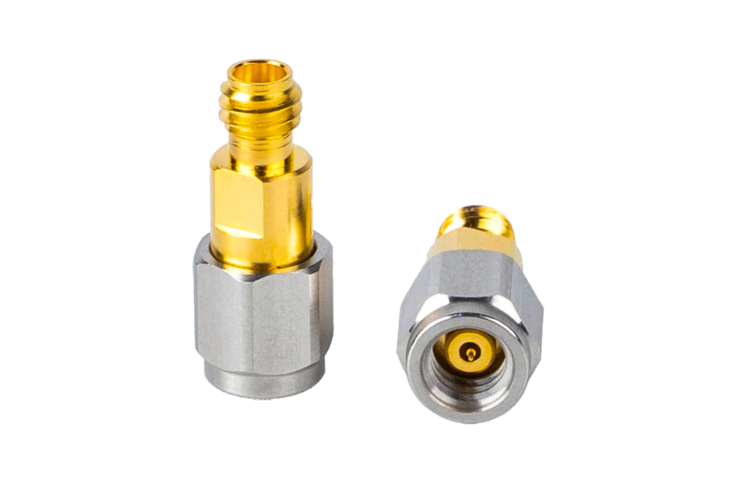
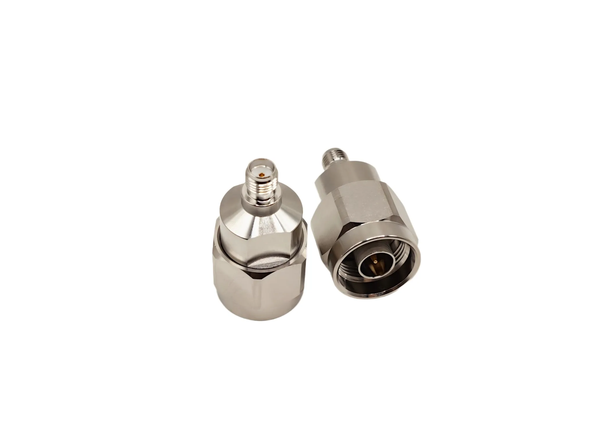
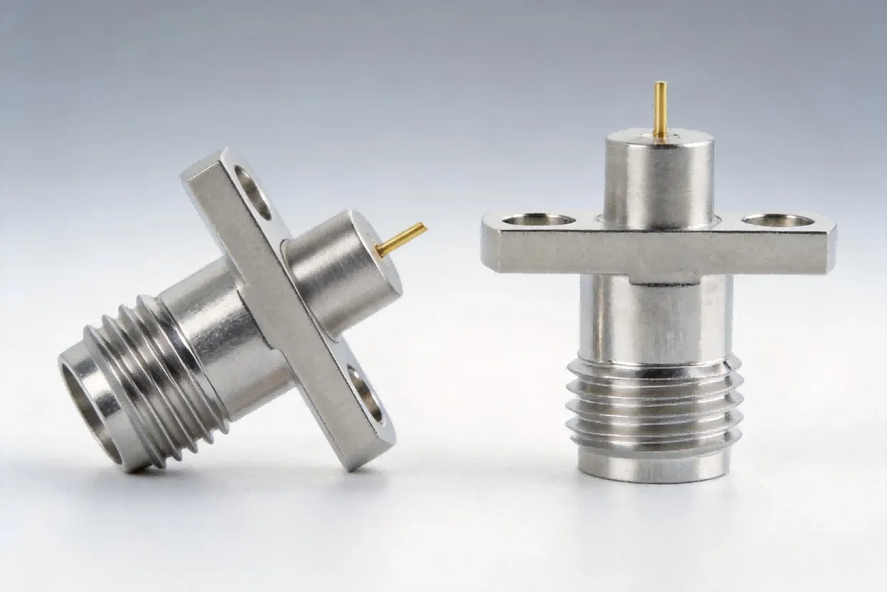
Coaxial Adapter connects different RF connector interfaces such as SMA, N, BNC, 3.5mm, 2.92mm, 2.4mm, 1.85mm and 1.0mm. Ideal for microwave test systems, RF instrumentation, satellite communication equipment and millimeter-wave measurement platforms.

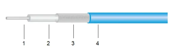
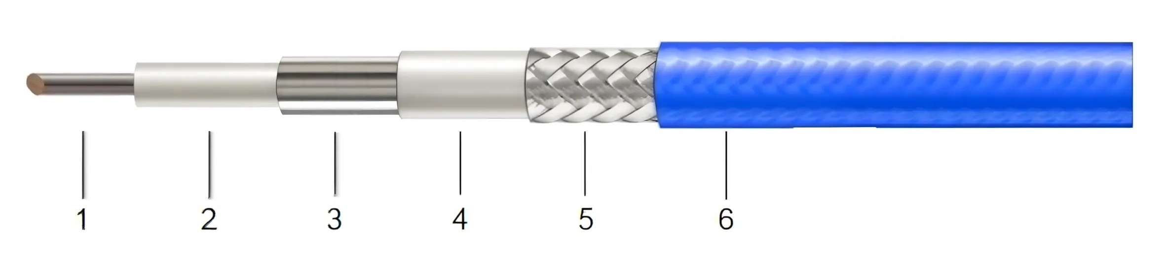
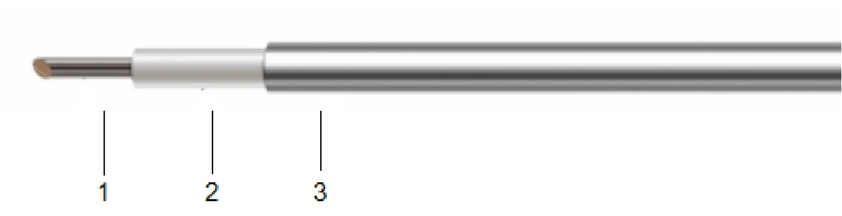
CSF Series semi-flexible coaxial cables solve dense interconnect challenges in phased array radar and ECM systems. OD from 1.19 mm (CSF047) to 6.85 mm (CSF250FEP). 100 dB shielding eliminates co-site interference. Silver-plated copper clad steel center conductor, PTFE dielectric, 40 GHz (CSF047/CSF086), 50 Ohm, 70% Vp. Hand-formable, 4 mm static bend radius. Unjacketed and FEP-jacketed variants with identical RF performance. -65 to +150 deg C. 500 to 3500 V DC withstand.

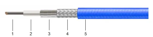
Facing signal dropouts, weathered cable cracking, or tight routing issues? AO Microwave’s CM Series communication cables protect your network. Encased in rugged, UV-resistant PUR jackets, these low-loss, low-VSWR cables prevent environmental degradation and costly downtime. Highly flexible (static bend radius down to 6.4mm) and built with solid copper/Foam PE cores, they ensure stable transmit power and smooth installation in base stations and vehicle networks up to 10 GHz.

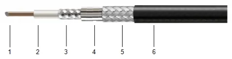
AO Microwave’s CB Series features low-loss, high-power flexible coaxial cables designed for transmitter feeds and telecom stations. Utilizing a solid PTFE dielectric and a robust FEP jacket, the series ranges from 4.60mm (CB460) to 14.70mm (CB1500) outer diameters. Its triple-shielded structure (silver-plated copper foil, aluminum laminate, and wire braid) provides >90 dB shielding. Stable under high CW power, making it suitable for base stations and RF testing

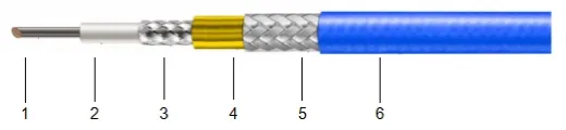
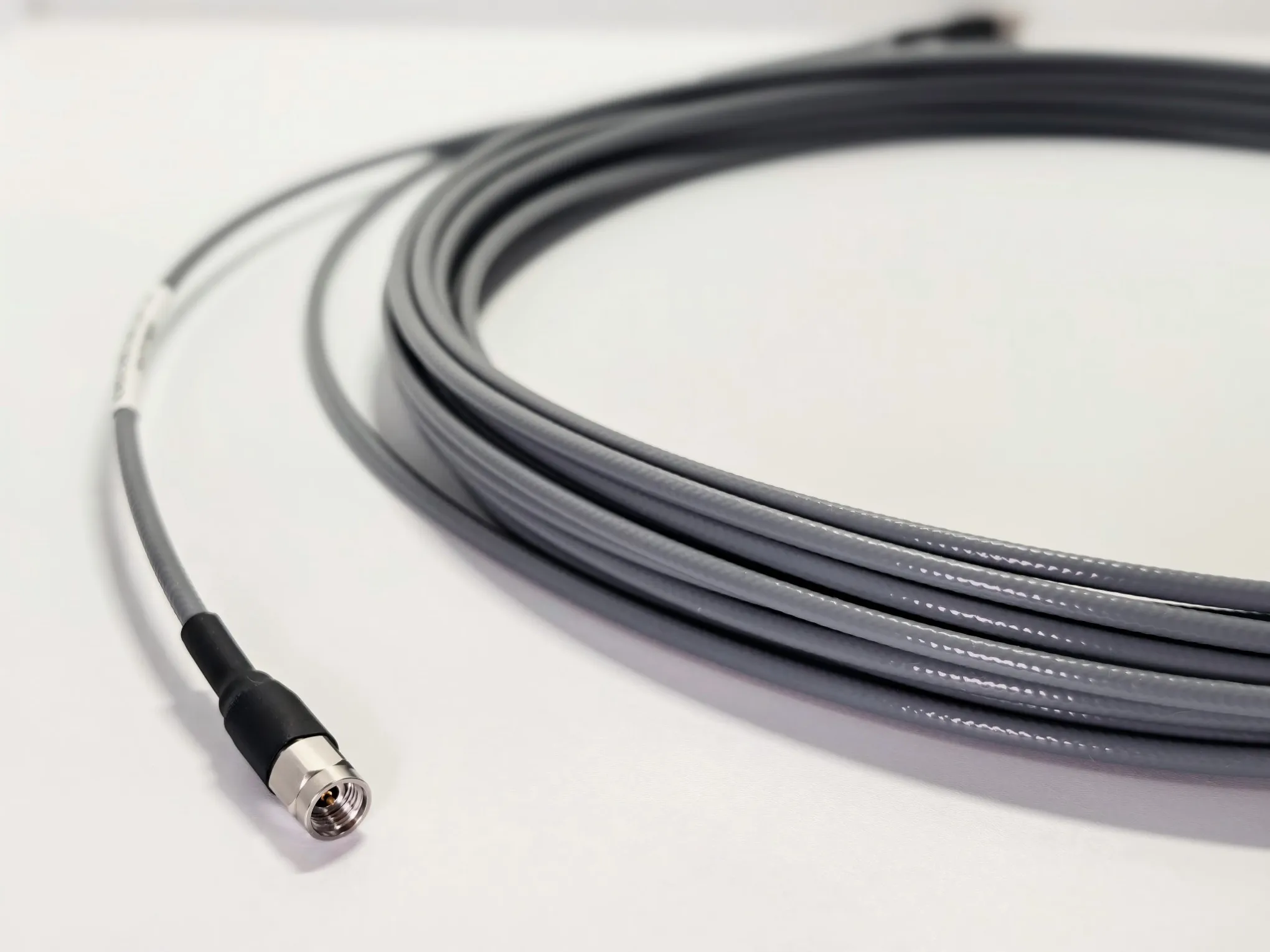
CC Series test-level coaxial cables from AO Microwave cover DC to 110 GHz across six models. Built on silver-plated copper conductors and dual-PTFE dielectric architecture, every CC cable delivers 50-ohm impedance, 90 dB shielding, and repeatable phase stability from -55 degree C to +165 degree C. Whether calibrating a VNA at 67 GHz or routing through a thermal chamber, CC Series gives your measurement chain the low-uncertainty, traceable performance that metrology-grade testing demands.

When avionics and electronic warfare systems demand RF cabling that survives -55C to +165C with 90 dB shielding, the CL Series eliminates guesswork. Nine models (2.33 to 9.40 mm OD) span DC to 40 GHz on one PTFE dielectric and FEP jacket platform. Stranded-conductor variants (CL520S, CL530S) absorb vibration without phase drift, while CL900 and CL940 handle 2.6 kW at 1 GHz for broadband jamming. Qualify the material set once and scale across your entire frequency ladder.

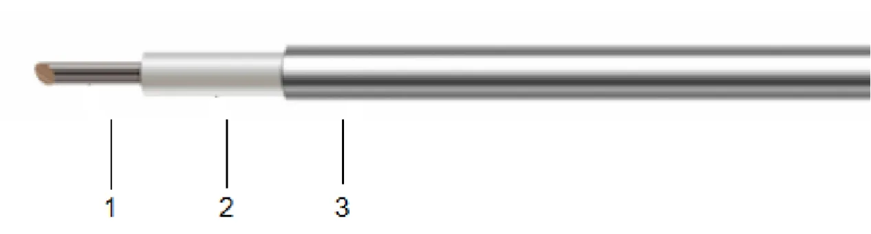
For dense RF packaging where flexible cables fail, CE Series semi-rigid cables hold their exact formed shape—eliminating phase drift and spring-back. Low VSWR and Low PIM ensure clean multi-carrier signals, while 165 dB shielding blocks crosstalk in tight enclosures. Six models cover DC to 40 GHz, with cost-optimized CN variants for 18 GHz systems. Bend radii down to 1.27 mm and weights from 2 g/m suit production-volume RF instrument interconnects, phased-array modules, and airborne payloads.

You're past 26 GHz and your cable is the weak link—phase drifts with temperature, leakage corrupts calibration. CF Series semi-rigid solves both: seamless copper tube with 165 dB shielding stops crosstalk at any routing density, and <750 PPM phase stability keeps VNA measurements repeatable all day. Three OD options (1.19–3.58 mm) fit a probe station or a phased-array backplane. Pre-formed assemblies ship tested and ready.

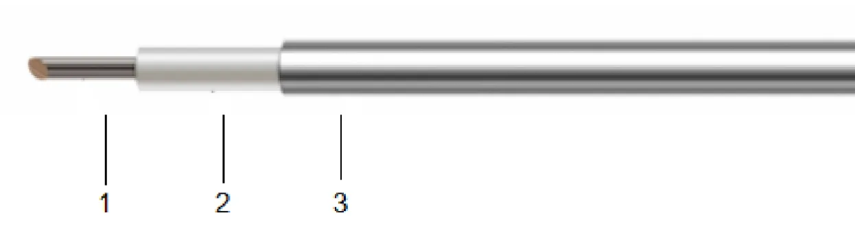
When flexible cables fail in dense RF instruments and phased arrays, CK Series semi-rigid cable delivers. Seamless copper tube achieves 165 dB shielding regardless of packing density. PTFE dielectric at 81% Vp with <750 PPM phase stability. CK086: 40 GHz in 2.18 mm OD, 7 mm bend radius. CK141: lower loss and 4x power to 26.5 GHz. Pre-formed, connectorized, VNA-verified assemblies. Contact sales@aomicrowave.com for your routing requirements.

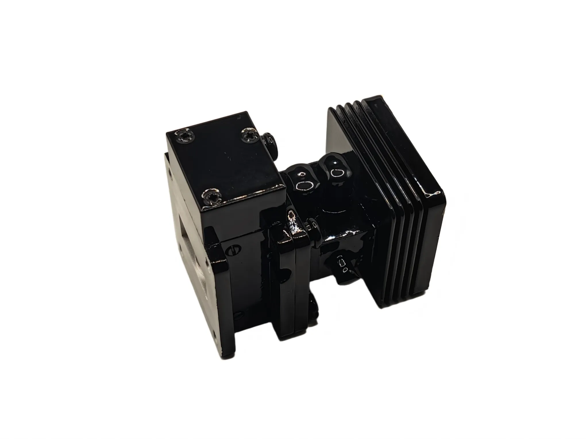
High-power waveguide circulator selection: peak vs average power, insertion loss, cooling methods, load sizing, flange compatibility, altitude derating. 10-point checklist with engineering rules.

Waveguide circulator failure guide: isolation drop, load burnout, flange leak, ferrite crack, frequency drift. VNA diagnosis, prevention for radar & SATCOM.

Waveguide circulators in radar AESAs and SATCOM gateways: TR module duplexing, N+1 redundancy, LEO constellation demands, and the peak-vs-average power distinction.

Waveguide circulator vs isolator: a side-by-side comparison of physics, specifications, and real-world use cases. Learn which component protects your power amplifier and which routes your signals.

What is a waveguide circulator? Learn how ferrite materials enable non-reciprocal RF routing, protect amplifiers, and allow duplexing in microwave systems.

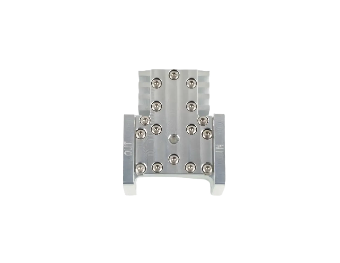
mmWave waveguide bend precision: why surface roughness >0.4 μm adds 38–86% loss at 94 GHz. Compare CNC, EDM & electroforming tolerances by frequency.

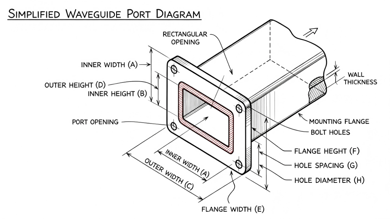
Looking for a custom waveguide bend manufacturer? Get the complete RFQ checklist, spec guide, and manufacturing process for E-bends and H-bends from AO Microwave.

Waveguide bend selection guide: E-bend, H-bend, and miter compared by VSWR (<1.10), insertion loss (<0.1 dB), and bend radius. Industrial vs aerospace grade cost analysis included.