
Circulators, Isolators and Limiters: The Complete Guide to Ferrite Routing and Receiver Protection
Waveguide circulators, isolators and limiters explained: ferrite routing, isolation and receiver protection. Quotes and datasheets in 24 hours.
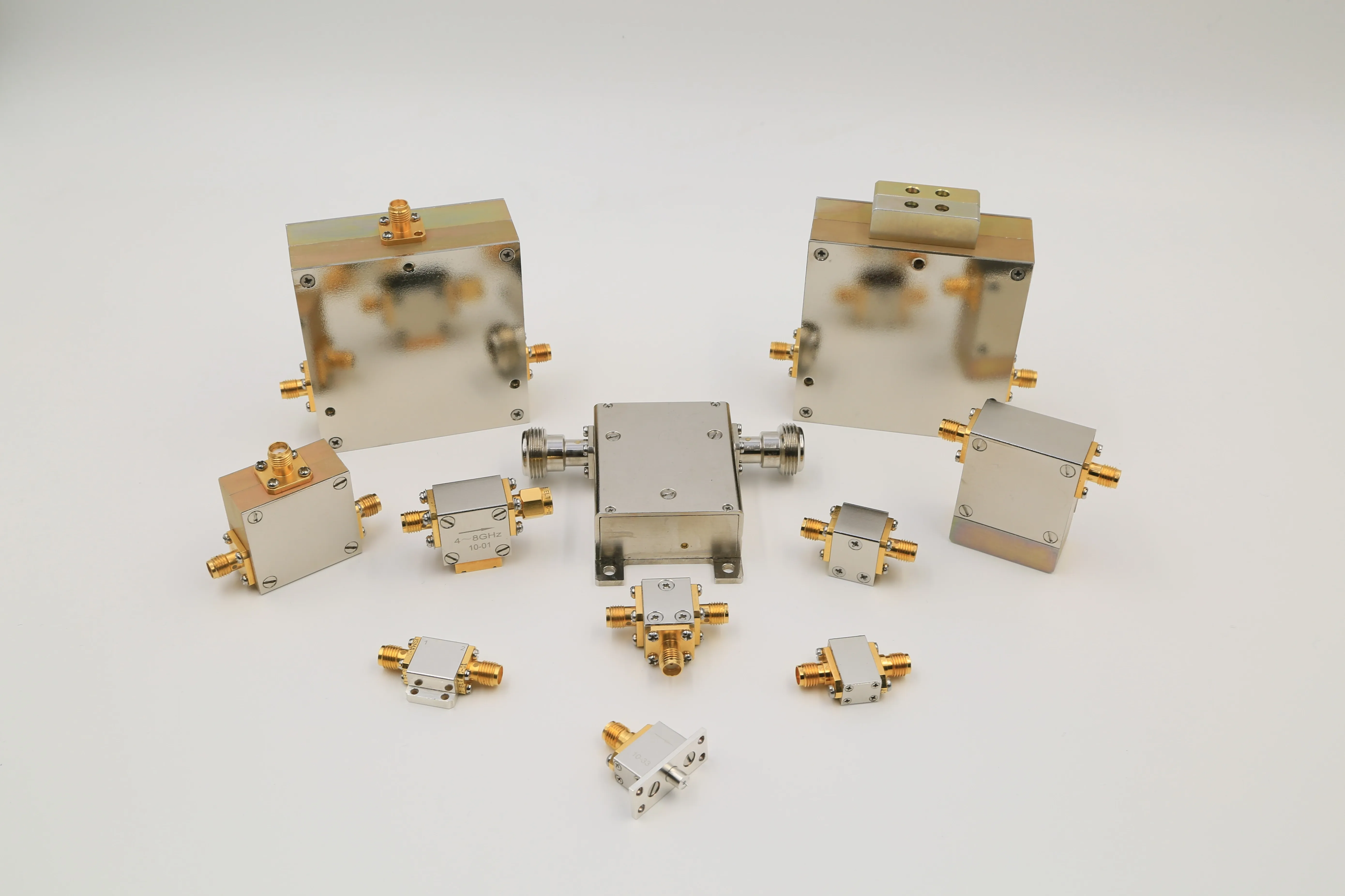
A circulator routes, an isolator protects the source, and a limiter protects the receiver — three jobs, one ferrite family. In a radar or satellite front end they usually appear together — circulator separating transmit from receive, isolator shielding the amplifier, limiter standing in front of the low-noise amplifier as the last line of defense. This guide pulls the family together — how the ferrite makes a signal travel one way, how the three devices differ, the four numbers that decide a selection, and where each earns its keep. Each section stays short; the deep dives are linked at the end.
If you already know your band and which of the three jobs you need, jump to the selection checklist; if you are still deciding between routing and clamping, start with the comparison table.
How a Circulator Works: Ferrite, Magnet and One-Way Traffic
A circulator is a non-reciprocal three-port device — four ports in some builds. Inside the junction sits a ferrite disc, usually yttrium iron garnet (YIG), biased by a permanent magnet, samarium-cobalt or neodymium. The magnetically biased ferrite has a tensor permeability, which makes a microwave signal travel differently depending on direction: energy entering Port 1 exits at Port 2, energy entering Port 2 exits at Port 3, and so on around the circle. The signal never goes backward. There are no moving parts, no control electronics and no power supply — the routing is built into the physics. The waveguide circulator guide works through the ferrite principle, the port routing, and the specifications that matter.
That one-way behaviour makes the circulator the duplexer in radar and satellite systems, letting one antenna transmit and receive at the same time. AO Microwave's waveguide circulator family is machined from solid aluminum or copper housings, uses YIG or nickel-zinc ferrites biased by samarium-cobalt or neodymium magnets, and covers standard bands up to 110 GHz (WR-90 to WR-10), with typical isolation above 20 dB per junction, insertion loss under 0.25 dB, and input VSWR under 1.20:1.
Circulator vs Isolator vs Limiter at a Glance
| Device | Ports | Job | What happens to reverse power | Where it sits |
|---|---|---|---|---|
| Circulator | 3 or 4 | Routes signals cyclically | Sent to another port, usually into a load | Antenna junction, TX/RX separation |
| Isolator | 2 | Protects the source | Absorbed in the internal termination load | Behind the amplifier or oscillator |
| Limiter | 2 | Protects the receiver | Clamped; only a bounded leakage passes | Immediately ahead of the LNA |
The distinction that matters most is what each device does to a high-power signal coming the wrong way. A circulator can keep a reflected signal away from your transmitter, but it does not reduce the level of an incoming high-power signal: a 1 kW pulse entering the receive port still arrives at the receiver at roughly 1 kW minus only the port isolation. For receiver protection against incident high power, routing is not enough — you need clamping. The three-way comparison of limiter, circulator and isolator lays out where each one sits and which problem each solves.
The Isolator Is a Circulator With a Terminated Port
Take a three-port circulator and terminate one port with a matched load, and you have an isolator: a two-port device that passes energy forward with low loss and absorbs anything coming back. The load dissipates the reflected energy as heat, so the source behind the isolator never sees it. That is why an isolator's power rating is really two ratings — forward throughput and reverse dissipation — and why the load must be sized for worst-case reflection, not typical. The short circulator-vs-isolator comparison states the relationship in one line, and the waveguide isolator guide works through the physics, the fields and the selection drivers for high-power use.
Isolation stacks. A single-junction isolator gives around 20 dB of reverse isolation — a 100:1 reduction in reverse power. Put two junctions in series in one housing and the isolation roughly doubles to around 40 dB (10,000:1), with some designs exceeding 70 dB. The trade is that insertion loss stacks too: roughly 0.5 dB becomes about 1.0 dB, while the VSWR stays the same. So the choice is never "more is better" — it is how much reverse attenuation your source actually needs, and how much insertion loss your link budget can spare. A concrete example makes the ratio real: if your amplifier pushes 100 W into a load that reflects 1%, about 1 W heads back, and a 20 dB isolator knocks that down to roughly 10 mW reaching the source. The single- vs dual-junction isolator guide puts the two head to head on isolation, loss, size and cost. AO Microwave's waveguide isolator family runs up to 110 GHz (WR-90 to WR-10), typically above 20 dB isolation — dual-junction models exceeding 40 dB — with insertion loss under 0.25 dB and VSWR under 1.20:1.
The Limiter: A Circuit Breaker, Not a Router
A waveguide limiter is a two-port passive device that sits in the receive path, immediately ahead of the LNA. Think of it as a circuit breaker for microwave signals: invisible during normal reception, it clamps any signal exceeding a defined threshold. In its common form it uses a self-biased PIN diode that is transparent at low signal levels — insertion loss stays under 0.5 dB — but conducts when a high-power pulse arrives, presenting a low impedance that reflects most of the energy back and lets only a controlled leakage through. It needs no external power: the diode rectifies its own bias current from the incident RF pulse. The waveguide limiter guide explains the PIN-diode mechanism, the leakage numbers, and the three specifications that matter.
Two leakage numbers define a limiter. Flat leakage is the steady-state power that bleeds through once the diode is fully conducting — typically +20 to +30 dBm (about 0.1 to 1 W). Spike leakage is the brief burst that punches through in the first few nanoseconds before the diode fully turns on, measured in ergs; GaAs LNA damage thresholds fall around 1–10 ergs. Both numbers must stay below the LNA's damage threshold. One example design in the guides specifies 20 mW flat leakage, 100 mW spike leakage, a 1 µs recovery time and an 8 kW peak rating — a genuine high-power limiter, not a test-bench component.
Placement is the whole point: the isolator or circulator lives near the source and antenna junction, handling duplexing and keeping reflected energy off the transmitter. The limiter lives immediately ahead of the LNA, because that is the only place it can intercept a high-power pulse before it reaches the most fragile stage in the chain. Protecting the source and protecting the receiver are two different problems — and only one of them is a limiter. AO Microwave designs waveguide limiters across the standard bands — WR90 (X-band), WR62 (Ku-band) and others — for radar and electronic-warfare front ends.
The Four Numbers That Decide the Choice
| Specification | What it protects | Typical figure | Red flag |
|---|---|---|---|
| Isolation | Source and receiver from reverse power | 20 dB per junction; ~40 dB dual-junction | Below 20 dB for a protection job |
| Insertion loss | Forward power and the heat budget | Typically under 0.25 dB (max 0.3 dB per spec table); 0.1–0.3 dB at Ku-band, 0.5–1.0 dB at Ka/V-band | Above 0.3 dB over 500 W average without a cooling plan |
| VSWR | Source from reflection | ≤1.20:1 typical (1.20:1 is about 0.8% reflected) | Above ~1.25:1 |
| Power handling | The device itself | 10 kW CW class (isolators, S–Ka); megawatt peak at S-band, tens of kW peak at Ka-band | Peak rating quoted at centre frequency, not the band edge |
At 10 kW, 0.5 dB means over 1 kW dissipated inside the junction; at 0.3 dB it is about 667 W; at 0.8 dB, about 1.68 kW. Above 500 W average power, target insertion loss of 0.3 dB or better; above 5 kW, anything above 0.3 dB demands active cooling.
And mind the peak-versus-average trap: a circulator rated for 1 kW average power does not automatically survive 10 kW peak. Average-power failure is thermal: the ferrite heats, magnet remanence drops, and isolation degrades gradually. Peak-power failure is dielectric breakdown: the electric field at the waveguide centre exceeds the ionization threshold and an arc forms in nanoseconds. Always specify peak handling at the minimum operating frequency, closest to cutoff: a WR-284 circulator (S-band, 2.6–3.95 GHz) handles roughly 6–10 MW peak at sea level, while a WR-28 version (Ka-band, 26.5–40 GHz) may handle only tens of kilowatts. The deep circulator-vs-isolator comparison settles the routing-versus-protection decision with a specifications table, and the high-power circulator selection guide works all six decision parameters through with derating rules.
A Six-Step Selection Checklist
Lock these in order before you request a quotation:
- Lock the operating band and the matching WR size first — circulators cover standard bands up to 110 GHz (WR-90 to WR-10), isolators from S-band through Ka-band; the waveguide size chart maps every standard guide to its range and inner dimensions.
- Pick the job: routing (circulator), source protection (isolator) or receiver protection (limiter) — and remember a circulator does not clamp.
- Set the isolation from the reverse power your source must never see: around 20 dB per junction, around 40 dB for dual-junction; check whether a sensitive source (oscillator, synthesizer chain) needs the dual.
- Set insertion loss from your heat budget, not the catalog minimum — and confirm the cooling method at the same time.
- Confirm peak power at the band edge and average power with derating: derate average power by about 25% for every 10°C above the 25°C reference — a circulator rated 1 kW at 25°C handles roughly 750 W at 35°C and 560 W at 45°C.
- Size the termination load for worst-case reflection with margin: a 10 kW system with 15 dB worst-case return loss reflects 320 W continuously, so the load needs at least a 480 W rating with the 1.5× safety factor — and a waveguide load to match.
AO Microwave's waveguide circulator family covers 3-port and 4-port configurations with typical isolation above 20 dB per junction, insertion loss under 0.25 dB and VSWR under 1.20:1; the waveguide isolator family adds the internal termination load, typically above 20 dB isolation with dual-junction models exceeding 40 dB. Datasheets are made for the model you ask about; every inquiry gets a quotation with a full datasheet within 24 hours. Standard configurations run three to four weeks, custom bands or flanges four to eight weeks, and there is no minimum order on standard models.
Where They Earn Their Keep
Radar first. Remove the circulator from an S-band air-surveillance radar or a Ku-band satellite gateway and two functions vanish at once: the transmit/receive duplexing that lets one antenna do both jobs, and the amplifier protection that stops reflected energy destroying output transistors on the first high-VSWR event. In an AESA radar, every transmit/receive module carries a miniature ferrite circulator, and at the subarray level larger waveguide circulators handle power distribution — a single X-band array of 1,500 elements at around 10 W each is 15 kW of GaN power that must be protected on every pulse. The radar and satellite applications guide covers duplexing, AESA, gateways and LEO handoffs.
Satellite gateways are the continuous-power case: uplinks run 500 W to 2 kW CW at Ku-band, so the circulator's internal load must dissipate reflected energy continuously, not just during pulse peaks. LEO gateways add handoffs every 5–10 minutes, which change pointing, polarization and antenna VSWR, so the load absorbs rapidly cycling mismatch hundreds of times a day. At Ka-band and V-band, waveguide keeps its isolation where coaxial solutions suffer dielectric loss, and the rigid air-dielectric structure stays stable across −40°C to +55°C ambient swings at remote gateway sites.
Electronic warfare and test round out the family: limiters protect SIGINT and ELINT receivers from hostile signals designed to overload them, and isolators keep reflected power from pulling oscillators in precision measurement, where 30 dB+ isolation is non-negotiable.
Keeping Them Healthy: What Goes Wrong Over Time
The most common slow failure is isolation degradation: isolation drifts from 20–25 dB down to 12–15 dB over months or years while the device still "works" — signals still route, but reverse-path leakage climbs until the receiver limiter fires more often or the power amplifier starts seeing elevated reflected power. The cause is usually the bias magnet losing remanence: a field drop of just 5% can cost 3–5 dB of isolation. Samarium-cobalt magnets lose less than 0.1% of remanence per year at room temperature, but around 1–2% per year at 150°C continuous, and with YIG ferrite's Curie point around 280°C, sustained operation at 120–150°C already accelerates the damage. Prevention and monitoring beat repair: specify extended-temperature ferrite grades above 85°C ambient, keep airflow around the housing, record a full S-parameter baseline at installation, and re-sweep annually — a 1–2 dB drift in a year may be acceptable, a 5 dB drift demands investigation. The other classic failures are termination load burnout and flange leakage with moisture ingress — verify flange compatibility before assembly, torque bolts in a diagonal cross-pattern, and seal outdoor installs. The circulator problems and prevention guide covers all three failure modes with a diagnostic table and a maintenance schedule.
Frequently Asked Questions
Q: Can a circulator protect my receiver from a high-power pulse?
A: No — routing is not clamping. A circulator keeps a reflected signal away from your transmitter, but a 1 kW pulse entering the receive port still arrives at the receiver at roughly 1 kW minus only the port isolation. Receiver protection needs a limiter immediately ahead of the LNA.
Q: Single-junction or dual-junction isolator — which should I order?
A: Order single-junction if around 20 dB of reverse isolation covers your worst-case reflection — it is smaller, lighter and lower loss. Order dual-junction if your source is sensitive to load pull (oscillators, synthesizer chains) or the reflected power is high: you get around 40 dB, but insertion loss roughly doubles (about 0.5 dB becomes about 1.0 dB) and the part is roughly twice the size and cost. VSWR is the same either way.
Q: Why is my circulator's isolation slowly dropping?
A: The usual cause is the bias magnet losing remanence with heat and age — a 5% field drop can cost 3–5 dB of isolation. Compare a fresh S-parameter sweep against the installation baseline; if the drift is 5 dB or more, investigate temperature history and consider replacement. Also check the termination load: a failing load shows up as poor isolation at one frequency only.
Keep Reading: The Circulator, Isolator and Limiter Library
Ten guides, one per angle. Start with the comparison, then follow the decision you are stuck on.
- Waveguide Circulator vs Waveguide Isolator: What's the Difference? — the deep comparison: definitions, the ferrite principle, a specifications table and selection.
- Circulators vs. Isolators: Understanding the Relationship and Key Differences — the short comparison: how an isolator is a circulator with a terminated port, and the key differences at a glance.
- What Is a Waveguide Circulator and How Does It Work? — the circulator definition: ferrite non-reciprocity, port routing, and the specifications that matter.
- What Is a Waveguide Isolator and Why Is It Important in RF Systems? — the isolator definition: the physics, the fields, and what drives selection for high-power use.
- How to Choose the Right Waveguide Circulator for High-Power RF Systems — the selection guide: six parameters, peak vs average power, cooling and derating.
- Common Waveguide Circulator Problems and How to Avoid Them — fault diagnosis: isolation degradation, load burnout, flange leakage, and the maintenance schedule.
- Why Are Waveguide Circulators Essential in Radar and Satellite Systems? — the applications: radar duplexing, AESA, SATCOM gateways and LEO handoffs.
- Waveguide Limiter vs Circulator vs Isolator: Which One Actually Protects Your Receiver? — the three-way comparison: routing vs source protection vs receiver protection, and where each sits.
- What Is a Waveguide Limiter and How Does It Protect RF Systems from High-Power Signals? — the limiter definition: PIN-diode clamping, flat vs spike leakage, and the three numbers that matter.
- What Is a Coaxial Dual-Junction Isolator, and When Should You Choose It Over a Single-Junction One? — the coaxial branch: single vs dual junction, isolation, loss, size and cost.
And the hardware itself: the waveguide circulator product page and the waveguide isolator product page — 3-port and 4-port circulators and single- and dual-junction isolators to 110 GHz, datasheets and quotations within 24 hours.
Specifying a Circulator, Isolator or Limiter?
Tell us your band, port configuration, and power level. We will confirm the ferrite grade, the junction count, and the lead time — and return a full datasheet with your quotation within 24 hours.
Contact Our Engineering TeamSources: the ten AO Microwave circulator, isolator and limiter guides linked above and the waveguide circulator and isolator product pages.