
Waveguide Switches: The Complete Guide to Types, Selection, and Applications
Waveguide switches explained: SPDT and DPDT types, latching vs failsafe, selection, and applications. Quotes and datasheets within 24 hours.
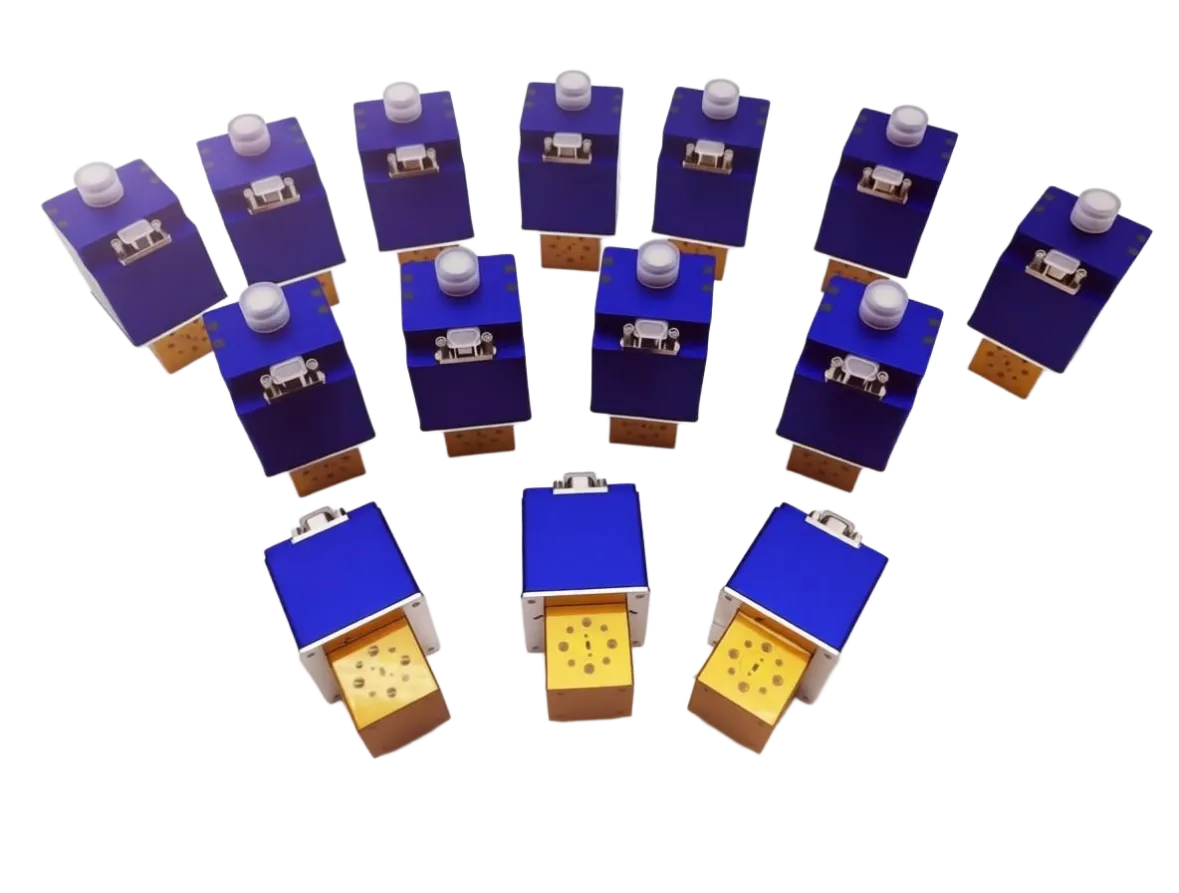
A waveguide switch moves an RF path from one port to another inside a hollow metal guide. It is a small part with an outsized job: when a transmitter fails, a test bench changes device, or a radar swaps chains, the switch is what keeps the system running without anyone touching a flange. This guide pulls the subject together — what the switch does, the two configurations, the actuator choice, the four numbers that decide a link budget, and where waveguide beats coaxial. Each section stays short; the deep dives are linked at the end.
If you already know your WR size and configuration, jump to the selection checklist; if you are still deciding between waveguide and coaxial, start with the crossover rule.
What a Waveguide Switch Does
Inside the housing (the stator) sits a machined rotor carrying curved waveguide channels. A command to the drive motor turns the rotor — usually by 90 degrees — disconnecting the signal from one output port and aligning the channel with another. Because the signal travels through a physical waveguide channel rather than a semiconductor junction, an electromechanical switch offers very low insertion loss and high power handling, making it the standard choice at microwave and millimeter-wave frequencies.
Three actuator families cover the work: manual switches, operated by hand for laboratory use; electromechanical switches, which use a motor or solenoid actuator to change path automatically and are the workhorse of automated test systems and redundancy builds; and PIN diode switches, which control the signal electronically with no moving parts for very fast switching — at the cost of the power handling an air-filled guide provides. The functions overview covers signal routing, antenna selection, equipment protection, and test-system configuration in detail.
SPDT vs DPDT at a Glance
Nearly every routing job comes down to two configurations. An SPDT (single pole double throw) switch has three ports — one input routed to either of two outputs — the right call when a single path needs selecting, such as feeding one transmitter to a primary or a backup antenna. A DPDT (double pole double throw) transfer switch has four ports and two paths that move together on one command, making it the heart of 1:1 redundancy: the main amplifier feeds the antenna while the standby sits on a load, and one command swaps both when the main unit trips.
| Configuration | Ports | Best for | Watch out for |
|---|---|---|---|
| SPDT | 3 — one path | Selecting one of two outputs (antenna routing, test routing) | Two units needed if two paths must move |
| DPDT transfer | 4 — two paths together | 1:1 redundancy, main and standby | Slightly larger body |
Two SPDT switches bolted together can imitate a transfer switch, but they double the flange count — every joint another place to leak, corrode, or lose a tenth of a decibel — and cannot hold phase repeatability the way one rigid transfer switch can. The waveguide switch overview works through both configurations and the four specifications that matter. A concrete example is the WR22 DPDT waveguide switch built for Q band: 30 to 50 GHz, 0.20 dB insertion loss, VSWR 1.20, and 50 dB isolation, latching.
Latching or Failsafe: What Happens When the Power Dies
The word "switch" hides a second decision that most datasheets mention in a single line and most engineers regret later. A latching switch takes a short pulse of control power to move and then stays put with no holding current — lower cost, higher mean time between failures, and usually a manual override. A failsafe switch returns to a spring-loaded default the instant control power disappears, so it needs continuous current to hold the active state; it costs more, the spring is the part that eventually drifts, and it usually cannot take a manual override.
One question settles the choice: what must the RF path be when the cabinet loses power? If losing power must produce a known safe route — dropping a transmitter onto a dummy load so a receiver stays protected — choose failsafe. If the last commanded state should be preserved and you would rather not dissipate holding current in an already warm enclosure, choose latching. Latching is the default in most builds; a long-running switch maker puts the commercial mix at roughly 98% latching. Either way, order position indicators and a manual override on any remote site, and confirm before wiring whether your controller expects a T circuit (two TTL lines) or a TA circuit (one line). The full decision table is in the latching vs failsafe waveguide switch guide.
The Four Numbers That Decide Your Link Budget
Two switches with the same drawing and the same "0.1 dB" headline can behave nothing alike. Four numbers separate them:
| Specification | What it protects | Red flag |
|---|---|---|
| Insertion loss | Forward power reaching the load | Quoted only at mid-band |
| Isolation | Receiver from transmit leakage | Below 40 dB at full power |
| VSWR | Source from reflection | Above 1.25:1 |
| Switching speed | Blind spot during rotation | No mute interlock specified |
Insertion loss is the number engineers quote first and feel last: a switch at 0.1 dB loses about 2.3 percent of forward power as heat, so 100 W through it leaves roughly 2.3 W to escape the housing. Isolation protects the receiver: 100 W (50 dBm) into a switch with 50 dB isolation leaves about 1 mW at the isolated port; at 30 dB the same port sees 100 mW. VSWR of 1.20 equals 20.8 dB return loss, about 0.8 percent reflected; at 1.25:1 the reflection rises to 1.2 percent. Switching speed sets the blind spot: a typical electromechanical switch moves in about 60 ms, during which the rotor is physically between ports. The deep selection guide works all four numbers through with a checklist.
Power Handling: Average, Peak, and Duty Cycle
Waveguide switches earn their keep at high average power: the signal travels through air and the heat spreads across the whole inner surface. The number that trips people up is the pulse: a 1 kW peak at 5 percent duty is only 50 W of average heating, yet the peak still has to survive the voltage. Size the switch against the average you dissipate, then confirm the peak and the pulse width — never let a quoted average hide a peak the cavity cannot take.
Where Waveguide Switches Earn Their Keep
The same four applications recur across the whole group. In satellite ground stations and gateways, switches route signals between antennas, amplifiers, and receivers and provide the 1:1 redundancy that keeps a link up when an amplifier fails. In defense radar, they route between transmitters, receivers, and antennas and swap redundant chains. In RF test and measurement, they connect devices under test to instruments such as vector network analyzers without recabling. In 5G and millimeter-wave work, Q-band switches route and mute signals on benches validating modules.
Waveguide or Coaxial: The Crossover Rule
Both devices move a signal from one port to another; the difference is the transmission structure. A waveguide switch routes energy through a hollow metal guide, so loss stays nearly flat into millimeter wave and the open port is blocked by a physical slab of metal, which is why 60 to 100 dB isolation is normal. A coaxial switch routes along a center conductor inside a dielectric: flexible, compact, and covering DC to 40 GHz and beyond in one connector family, but its dielectric loss climbs with frequency and the thin center conductor concentrates the power.
| Parameter | Waveguide switch | Coaxial switch |
|---|---|---|
| Transmission | Hollow metal guide, air | Center conductor plus dielectric |
| Frequency | Band-limited per WR size | DC to 40+ GHz in one family |
| Power handling | Several kW average, very high peak | Hundreds of W to a few kW average |
| Insertion loss trend | Flat into millimeter wave | Rises with frequency |
| Isolation | 60 to 100 dB | 60 to 80 dB |
| Form factor | Rigid, flanged | Compact, flexible |
| Best use | High power, millimeter wave, radar, satcom | Low frequency, test, flexible routing |
The practical line sits around 20 to 40 GHz and a few kilowatts average: above it, waveguide; below it, coaxial wins on flexibility and cost. Real systems are usually hybrid — waveguide on the high-power transmit path, coaxial on the auxiliary calibration and monitoring lines. Speed favors coaxial solid-state versions, but tens of milliseconds is fast enough for any redundancy or test-routing job that is not pulse by pulse. The full comparison is in the waveguide vs coaxial switch guide. For the coaxial side of a hybrid build, AO Microwave's coaxial switch family covers the flexible-routing end.
Keeping a Switch Alive: Installation and Maintenance in Brief
Use calibrated torque tools and follow the flange torque specification — typically 0.5 to 1.5 N·m by flange size — because improper torque stresses the internal mechanism. Keep the environment inside the typical operating range (about -10 °C to +50 °C, below 70% relative humidity, non-condensing). Align flanges with pins where applicable; even a small misalignment loads the rotor. Inspect flange surfaces, screws, and RF performance on a schedule, and never run above the rated power — exceeding it arcs inside the guide and damages the cavity. Latching types are rated beyond one million mechanical cycles within their voltage and environmental limits, and life drops sharply if the switch is hot-switched or driven outside its control range. The guide to extending a waveguide switch's lifespan covers each practice in detail.
A Six-Step Selection Checklist
Lock these in order before you request a quotation:
- Lock the operating band and the matching WR size first — the family runs from WR-137 to WR-10, roughly 5.85 to 110 GHz; the waveguide size chart maps every standard guide to its range and inner dimensions.
- Pick SPDT or DPDT from whether one path or two must move.
- Decide latching or failsafe from what the path must be when power fails.
- Set insertion loss, isolation, and VSWR from your link margin, not the catalog minimum.
- Confirm average power, peak power, and duty cycle with margin.
- Verify flange style, position indicators, and a manual override if the site is remote.
AO Microwave's waveguide switch family covers SPDT and DPDT configurations in latching or failsafe builds, with standard bands up to 110 GHz — aluminum and copper alloys, solenoid actuators, self-locking mechanisms, and micro-switch position indicators, specified at typically above 60 dB isolation, below 0.15 dB insertion loss, and below 0.05° phase repeatability. Datasheets are made for the model you ask about; every inquiry gets a quotation with a full datasheet within 24 hours. Standard configurations run three to four weeks, custom bands or flanges four to eight weeks, and there is no minimum order on standard models.
Frequently Asked Questions
Q: Can I switch a waveguide switch while RF power is running through it?
A: No. Switching under live RF — hot switching — opens an air gap as the rotor turns, and the voltage breaks down into an arc that carbonizes the cavity and permanently raises insertion loss. Always mute the RF source for the brief rotation window (about 60 ms) before you command a change.
Q: Latching or failsafe — which actuator should I order?
A: Order latching if the selected path should be retained with no holding current and no extra heat — it suits standby transmitters and remote sites. Order failsafe if a loss of control power has to produce a known RF state, such as dropping a transmitter into a load to shield a receiver. Both can be supplied with position indicators and a manual override.
Q: How long will an electromechanical waveguide switch last?
A: Latching types are rated beyond one million mechanical cycles within their specified voltage and environmental limits. Life drops sharply if the switch is hot-switched or driven outside its control range, so the rating assumes cold switching. The actuator is rarely the first thing to fail; control wiring, connector torque, and dust cause more field problems than the rotor.
Keep Reading: The Waveguide Switch Library
Eight guides, one per angle. Start with the overview, then follow the decision you are stuck on.
- Securing Mission-Critical Uptime: Waveguide Switches Explained, Types, and RF Applications — the overview: how SPDT and DPDT switches work, the four specifications that matter, and how redundancy keeps a link online.
- What Are the Functions and Applications of Waveguide Switches? — the functions: signal routing, antenna selection, equipment protection, and test-system configuration, and where switches are used.
- How Do You Choose a Waveguide Switch When the Datasheets All Look Alike? — the deep selection guide: five decisions, the four link-budget numbers, power handling, and a six-step checklist.
- How to Choose the Right Waveguide Switch? — the short selection guide: frequency range, switching type, insertion loss, isolation, power handling, and mechanical reliability.
- How Do You Keep a Q-Band Link Alive When a Transmitter Fails? Meet the WR22 DPDT Waveguide Switch — the case study: a WR22 DPDT transfer switch at 30 to 50 GHz, its measured numbers, and where Q-band switches earn their keep.
- Latching or Failsafe Waveguide Switch: What Happens When the Power Dies? — the actuator decision: latching vs failsafe, T vs TA control circuits, and a decision table.
- How to Extend the Lifespan of a Waveguide Switch? — the maintenance guide: installation torque, environment, alignment, inspection, and power limits.
- Waveguide Switch or Coaxial Switch: Which One Should Route Your RF? — the comparison: where waveguide wins on power, loss, and isolation, where coaxial wins, and the crossover rule.
And the hardware itself: the waveguide switch product page — SPDT and DPDT switches with standard bands up to 110 GHz, datasheets and quotations within 24 hours.
Specifying a Waveguide Switch?
Tell us your band, configuration, and control interface. We will confirm the flange, the actuator, and the lead time — and return a full datasheet with your quotation within 24 hours.
Contact Our Engineering TeamSources: the eight AO Microwave waveguide switch guides linked above and the waveguide switch product page.