
Waveguide Loads: The Complete Guide to Terminations, Selection, and High-Power Testing
Waveguide loads explained: matched terminations, high-power vs standard, sizing, and VSWR. Quotes and datasheets within 24 hours.
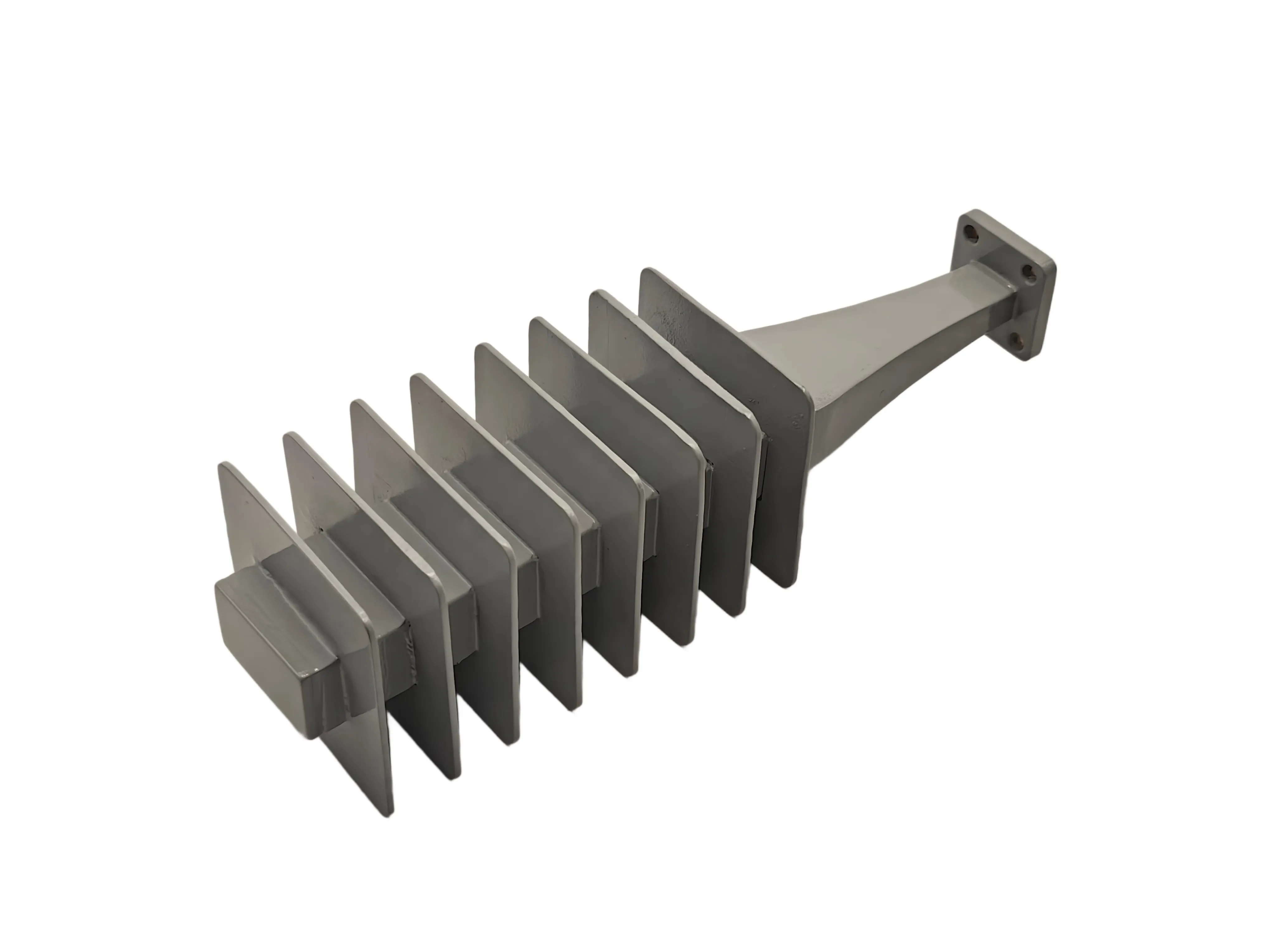
A waveguide load is the component that gives RF energy a safe place to stop. It is a one-port device at the end of a transmission path: every watt that enters is converted to heat inside a tapered absorber, and nothing comes back toward the source. When a port is left open instead, the energy reflects entirely, VSWR spikes, measurement data corrupts, and in a high-power chain the reflected wave can destroy the amplifier that produced it. This guide pulls the subject together — what a load does, standard versus high-power, the VSWR numbers that actually matter, how to size one without over-engineering, and two real builds at 100 W and 20 kW. Each section stays short; the deep dives are linked at the end.
If you already know your WR size and power level, jump to the selection checklist; if you are deciding how much VSWR precision your application really needs, start with the VSWR sweet spot.
What a Waveguide Load Does
Inside the metal housing sits a precisely shaped absorptive element — typically a tapered ceramic wedge impregnated with highly resistive compounds such as carbon or silicon carbide. The taper matters: it lets the wave enter gradually, so the impedance changes smoothly instead of hitting a wall and reflecting. The RF energy is forced through the resistive material and converted entirely into heat. A perfect load has a VSWR of 1.0:1; in practice, the quality of a load is measured by how close it gets, and by how much heat it can shed before the absorber cracks.
An open port is the opposite of a load. The wave meets a boundary of effectively infinite impedance and reflects entirely backward. The standing wave that results corrupts VNA calibration data, distorts phase, and leaks into receiver circuits. In a transmitter chain the reflected power returns to the output stage, where it can cause thermal overload and arcing within milliseconds. The load exists so that energy always has somewhere safe to go.
Three jobs recur across the whole group. First, terminating multi-port devices: the isolated port of a directional coupler, an unused output of a waveguide switch, or a circulator port must be capped with a matched load, or the reflection destroys the device's directivity and the measurements behind it. Second, VNA calibration: a precision load is the "Match" standard in TRL or SOLT calibration kits, the reference point for zero reflection — if it is wrong, every measurement after it is wrong. Third, redundancy: in a 1:1 satcom system the standby amplifier is routed into a load, staying powered and warm without broadcasting, ready to take over instantly. The waveguide load definition guide works through the absorption physics and all three applications in detail.
Standard or High-Power: The First Decision
"Load" and "termination" are used interchangeably in the field, but engineers generally split the family by power handling — and the split is really about thermal management, not RF performance. A standard load and a high-power dummy load both absorb; what differs is how fast each can get rid of the heat.
| Type | Power (CW) | Thermal design | Best for |
|---|---|---|---|
| Standard load (matched termination) | Typically 0.5 to 50 W | Smooth compact housing, natural heat dissipation, no fins | Capping coupler, switch, and circulator ports; VNA calibration |
| High-power load (dummy load) | 100 W to several kW | Finned housing, forced air, or liquid cooling | Absorbing a transmitter's full output during offline testing |
Choosing wrong fails in two directions. A standard load in a high-power job overheats: the absorptive element cracks or melts, the load becomes an open circuit, and the full reflected power returns to the transmitter. Over-specifying the other way wastes mechanical space and budget on a finned dummy load where a compact termination would do. The high-power vs standard waveguide load comparison sets the two side by side, and the terminations and loads explainer covers the thermal engineering — finned aluminum housings, forced-air fans, and copper or brass bodies for the hottest continuous-wave jobs.
The VSWR Sweet Spot: How Much Precision Do You Actually Need?
VSWR is the number that separates a good load from a decoration, and it is also the number most often over-specified. Achieving ultra-low VSWR takes CNC machining time and meticulous tuning of the absorber, which costs money — so the right target depends on what the load is protecting. Precision calibration loads hold a return loss better than 35 dB, a VSWR below 1.03:1. A general transmitter dummy load does not need that.
| Application | Recommended VSWR | Why |
|---|---|---|
| VNA calibration & metrology | < 1.03:1 | The load is the absolute reference; any reflection skews every measurement after it |
| Satcom 1:1 redundancy isolation | < 1.10:1 | Excellent absorption to stop leakage into the active path, without laboratory-grade perfection |
| General transmitter dummy loads | 1.15:1 to 1.20:1 | The job is safe heat dissipation; 1.15 is more than enough to protect the source |
The arithmetic keeps the targets honest. A VSWR of 1.20:1 is 20.8 dB return loss — about 0.8 percent reflected, so 100 W in sends roughly 0.8 W back. At 1.25:1 the reflection is about 1.2 percent, which is roughly 250 W coming back from a 20 kW transmitter. And the number that matters is the worst case across the whole band, not a typical value at mid-band. Power and precision also trade against each other: the standard catalog WR28 model holds 1.03:1 at 1 W, while the 100 W high-power WR28 build holds 1.20:1 — a looser match, but one that survives a hundred times the power. The sizing guide works the VSWR-versus-budget trade-off through in full.
Sizing Without Over-Engineering: A Five-Step Checklist
Lock these in order before you request a quotation:
- Lock the operating band and the matching WR size first — the family runs from WR-2300 to WR-10, roughly 0.32 to 110 GHz; the waveguide size chart maps every standard guide to its range and inner dimensions.
- Set average power, then confirm peak power and duty cycle with margin — a load that survives 60 kW pulses may still fail at 20 kW continuous, because average power is what heats the absorber.
- Set the VSWR from the application, not the catalog minimum — use the sweet-spot table above; paying for 1.03 when 1.15 would do is over-engineering.
- Check the mechanics: flange style (UDR, UBR, or cover/choke for standard bands; precision anti-cocking flanges such as UG-387/U with alignment pins above 40 GHz), housing material (aluminum for light weight, copper or brass for roughly double the thermal conductivity in confined high-power CW jobs), and whether the body actually fits the enclosure with airflow.
- Derate for the real environment — datasheet power ratings assume roughly 25 °C at sea level, and altitude, enclosure airflow, and ambient temperature all change the number. Confirm the derating with the supplier before ordering.
AO Microwave's waveguide load family covers the standard catalog from WR-2300 to WR-10 (0.32–110 GHz), 0.5–20 W, with VSWR from 1.03:1 at the lower bands to 1.15:1 at the millimeter-wave end, in lightweight aluminum and high-power copper bodies with UDR/UBR flanges. High-power and custom builds go beyond the catalog — the two cases below are the proof. Datasheets are made for the model you ask about; every inquiry gets a quotation with a full datasheet within 24 hours. Standard configurations run three to four weeks, custom builds four to eight weeks, and there is no minimum order on standard models. For coaxial lines, the coaxial load family covers the same terminating job in connectorized form.
Precision at Millimeter Wave
At low frequencies a small machining error is invisible to the wave. At 3 GHz the wavelength is about 100 mm, so a 0.1 mm error is 0.1 percent of it. At 110 GHz the wavelength shrinks to 2.7 mm, and that same 0.1 mm error is nearly 4 percent of the wavelength — to the wave, a tiny burr looks like a wall. That is why millimeter-wave loads are a different manufacturing problem from a WR-90 dummy load.
Three things decide whether a mmWave load holds its match: the geometry of the absorptive taper (at W-band the WR-10 cavity is only 2.54 × 1.27 mm, and the ceramic taper must fit inside it without touching the walls); the internal surface finish (at 110 GHz current flows only in a microscopically thin skin layer, so chatter marks or scratches on the inner wall raise resistance and shift phase before the wave even reaches the absorber); and flange alignment (a misaligned flange at these wavelengths is itself a reflection). The millimeter-wave precision guide works through all three with the wavelength arithmetic.
Two Real Builds: 100 W at 40 GHz and 20 kW Water-Cooled
The WR28 high-power load closes a gap on Ka-band benches, where typical catalog WR28 terminations are rated for fractions of a watt to a few watts — fine behind a signal generator, useless behind a power amplifier. The AO build covers the full 26.5–40 GHz band, absorbs 100 W average continuous-wave power, holds VSWR at or below 1.20:1 across the band, and runs 135 mm long on a standard UG-599/U square cover flange. The length is the thermal story: at 100 W through a WR-28 aperture of only 7.112 × 3.556 mm, the absorber needs room to spread heat along the guide and the body needs surface to conduct it away. It is the load for amplifier burn-in and soak testing, transmitter testing into a known impedance instead of an antenna, and terminating spare ports on circulators, isolators, and switches in a full-power rack. The WR28 100 W case gives the full numbers, including why 1.20 VSWR beats the 1.25:1 that catalog 100 W WR28 terminations commonly carry.
The WR90 water-cooled load is the other end of the scale: a custom build for full-power X-band transmitter testing, rated 20 kW average and 60 kW peak (500 µs pulse width, 30% duty cycle) across 8.5–11.0 GHz, with a maximum VSWR of 1.25 across the band, FBP100 cover / UBR100 flanges, and a 765 mm aluminum body. At 20 kW continuous no finned body survives on convection alone, so coolant runs through a jacket around the body — water's specific heat of about 4,180 J/(kg·K) carries away heat that would destroy the absorber — and the cooling system must be running before any RF power is applied. The build took three design revisions and two months from design to delivery, shipped in a custom plywood crate with a long wrench for the FBP100 bolts. The WR90 20 kW case is a customer case, and it doubles as a checklist: average versus peak, VSWR across the whole band, cooling interface, and delivery certainty.
Where Loads Earn Their Keep
The same five applications recur across the group. In satellite communications, loads sit in 1:1 redundancy matrices behind DPDT transfer switches, absorbing the standby amplifier. In EMC and EMI testing, they terminate high-power lines inside anechoic chambers so stray energy never reflects back into an immunity measurement. In defense and radar, they absorb megawatt-scale peak power while transmitters are calibrated at full output. In medical linear accelerators, they absorb residual S-band energy so radiation dosing stays precise. And in every RF laboratory, a precision load is the reference the VNA trusts. The terminations and loads explainer covers these applications, and the five-step specifying guide turns them into a repeatable selection process.
Frequently Asked Questions
Q: What is the difference between a waveguide load and an attenuator?
A: An attenuator reduces power but still lets a controlled portion pass through to the next stage. A load absorbs essentially all of the incident power. If you need to sample or split power for a following circuit, use a coupler or attenuator; if you need to absorb power at the end of a chain, use a load.
Q: If my amplifier feeds a load, do I still need an isolator?
A: A load absorbs power at the end of the line; an isolator protects a source from power reflected by anything downstream — antennas, switches, or a faulty connection. Many full-power racks use both: the isolator guards the amplifier from surprises, and the load gives reflected energy a safe place to go.
Q: Can I apply RF power before the water cooling is running?
A: No. The cooling system must be running before RF power is applied — even a brief dry run can permanently damage the absorbing element. Build a flow interlock into the setup so power cannot start without coolant flow.
Q: How much power can an air-cooled load take?
A: As a rule of thumb from the high-power guides, natural convection is practical up to a few hundred watts, forced-air designs reach a few kilowatts, and beyond that water cooling is the reliable option.
Keep Reading: The Waveguide Load Library
Eight guides, one per angle. Start with the definition, then follow the decision you are stuck on.
- Are Unmatched Ports Corrupting Your Data? What Is a Waveguide Load and Why Is It Important in RF Systems? — the definition: what a load is, how absorption works, and the three jobs that make it mandatory.
- Are You Risking Thermal Meltdown? High Power vs Standard Waveguide Loads: What’s the Difference? — the comparison: thermal design, power ranges, and the cost of choosing wrong.
- Stop Over-Engineering: The Smart Guide to Sizing and Selecting Waveguide Loads for RF Systems — the sizing guide: four trade-offs — material, derating, VSWR, and form factor.
- The Hidden Cost of Mismatched Terminations: A Strategic Guide to Specifying Waveguide Loads — the specifying guide: five steps from WR size to flange and lead time.
- Are Reflected Signals Threatening Your Amplifiers? Waveguide Terminations and Loads Explained for Ultimate RF Reliability — terminations vs dummy loads, thermal management, and industry applications.
- Are Microscopic Errors Corrupting Your 110 GHz Data? Why Precision Matters in Millimeter-Wave Waveguide Loads — mmWave precision: wavelength, taper geometry, surface finish, and flange alignment.
- How Do You Handle 100 W at 40 GHz? Meet the WR28 High-Power Waveguide Load That Stays at 1.20 VSWR — the case: a 100 W Ka-band load at 26.5–40 GHz in a 135 mm body.
- How Do You Safely Dissipate 20 kW of RF Power? Inside a Custom WR90 Water-Cooled Waveguide Load — the case: a custom 20 kW average / 60 kW peak water-cooled build for X-band transmitter testing.
And the hardware itself: the waveguide load product page — 29 models from WR-2300 to WR-10, 0.5–20 W, with a Quote link on every model, datasheets and quotations within 24 hours.
Specifying a Waveguide Load?
Tell us your band, power level (average and peak), and flange type. We will confirm the match, the cooling, and the lead time — and return a full datasheet with your quotation within 24 hours.
Contact Our Engineering TeamSources: the eight AO Microwave waveguide load guides linked above and the waveguide load product page.